Frame relay switched data service

a data service and frame relay technology, applied in data switching networks, time-division multiplexing selection, multiplex communication, etc., can solve the problems of large-scale highly-meshed networks that are difficult to implement, maintain and manage using conventional network technologies, and create a large burden on both network providers, so as to increase network speed, improve data security, and increase network security

Inactive Publication Date: 2007-08-14
AMERICAN TELEPHONE & TELEGRAPH CO
View PDF251 Cites 13 Cited by
  • Summary
  • Abstract
  • Description
  • Claims
  • Application Information

AI Technical Summary

Benefits of technology

[0016]A new type of data transport service takes advantage of the existing base of frame relay customer premises equipment (CPE) and customers while offering a new mechanism for providing extensible service features to those customers. In the new service, data link connection identifiers (DLCIs) may be used by the CPE to select among service types, feature sets, and closed user groups (CUGs). The DLCI is used in the layer 2 frame that conveys the user data to the network. The layer 3 user data packet is extracted from the layer 2 frame and the layer 3 address information for the (routable) protocol is used to route the user data packet over a high-performance packet switched network, according to the service class / feature set selected by the DLCI. At the destination, the layer 3 data packet is again enclosed in a layer 2 frame with a DLCI that indicates to which service group it belongs. The frame is then forwarded to the CPE. Use of this technique will allow the existing frame relay CPE to support, over the same physical interface, conventional frame relay service with a range of DLCIs that are linked to logical paths such as permanent virtual circuit (PVCs), as well as a range of DLCIs that are linked to service and / or feature sets. This will allow a robust method for extension of new services to the frame relay installed base, with minimal impact to existing customer equipment.
[0017]In some aspects of the invention, frame relay DLCIs are used for selecting among various “service categories.” This differs significantly from conventional frame relay, which uses DLCIs only to select PVCs and / or switched virtual circuits (SVCs). Service categories may include, but are not limited to, communication via the public internet, communication via a local intranet, communication within a closed user group (CUG), communication with an extranet (e.g., a network of trusted suppliers or corporate trading partners), live audio / video transmission, multicasting, telephony over internet protocol (IP), or any combination thereof. Thus, the concept of a frame relay PVC is significantly expanded by aspects of the present invention. For example, the location of an intended network endpoint recipient is not necessarily determined by a DLCI at a sending network endpoint. The DLCI may represent a service category with the intended recipient indicated by an IP address within the frame relay packet. This results in a significant benefit to network customers because, unlike that of conventional frame relay, customers no longer need to update their local DLCI tables each time a network customer with whom they wish to communicate is added or removed from the network. Thus, the customer's burden of network administration is substantially reduced.
[0019]In further aspects of the invention, addressing contained in multiple layers (e.g., as defined by the Open System Interconnection model) are compared with each other in a network to determine routing errors. If the addressing in the layers are consistent with each other, then the associated data is routed without interruption. On the other hand, if the addressing in the layers is inconsistent with each other, the associated data may be specially handled. For example, the data may be discarded, sent to a pre-determined address, and / or returned to the sender. This address comparison may be applied to the sending address and / or the destination address. An advantage of this multiple layer address comparison is that network security is increased. For instance, problems such as “spoofing,” which is the practice of purposely providing an incorrect sending internet protocol (IP) address, are better controlled by such a method.
[0020]In still further aspects of the invention, routing look-up tables within the network are separated such that, for example, each customer, closed user group (CUG), extranet, and / or intranet may have its own private partition and / or separate table. This can provide greater network speed because a router need not scan the entire available address space for all network customers at once. Furthermore, data security is improved because the risk of sending data to a wrong recipient is reduced.

Problems solved by technology

However, large-scale highly-meshed networks can be difficult to implement, maintain, and manage using conventional network technologies.
The conventional meshed frame relay network discussed above has a number of limitations.
For large networks with thousands of end user locations, this ripple effect creates a large burden on both the network provider to supply enough permanent virtual circuits (PVCs) and on the network customers in updating all of their routing tables.
Further, most routers are limited to peering with a maximum of 10 other routers which makes this network topology difficult to implement.
The result is a growth in the number and mesh of PVCs in networks that does not scale well with current network technologies.
However, VPNs are not widely supported by internet service providers (ISPs), have erratic information rates, and present a number of security concerns.
Further, because the tables mapping IP addresses to SVC addresses are typically manually maintained, SVCs are often impractical for large highly-meshed networks.
Further, frame SVCs are difficult to interwork with asynchronous transfer mode (ATM) SVCs.
None of the above solutions adequately address the growing demand for large mesh networks.

Method used


Image

  • Frame relay switched data service
  • Frame relay switched data service
  • Frame relay switched data service

Examples


Embodiment Construction

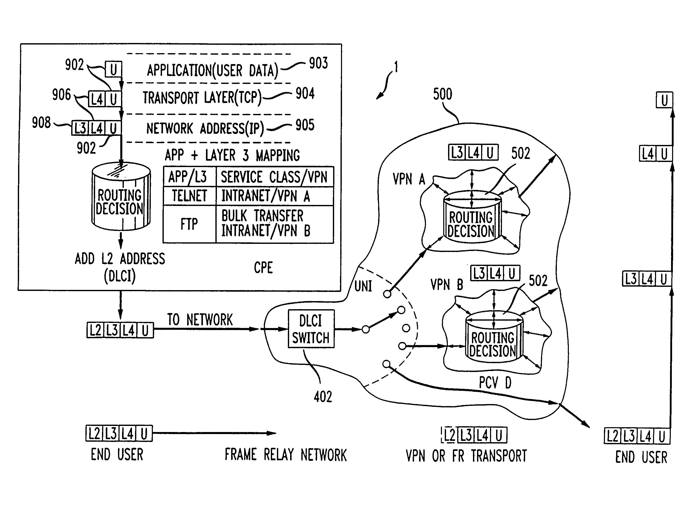
[0035]Exemplary embodiments of the present invention allow the large installed base of frame relay customer premises equipment (CPE) to be maintained by using the same interface in a different way to deliver new sets of services and features to the customer. For example, the data link connection identifier (DLCI) known from the frame relay protocol may be used to select among several virtual private networks with differing address spaces, feature sets, and / or conventional permanent virtual circuits (PVCs).

[0036]Referring to FIG. 7, a block diagram of a wide area network (WAN) 1 incorporating aspects of the present invention is shown. The WAN 1 includes a plurality of customer premises equipment (CPE), for example routers located at each of the end user locations and interconnected via one or more service provider's networks (SPNs) 500. The SPN 500 is typically connected to a plurality of endpoint routers 919 via a plurality of corresponding user network interfaces (UNIs) 402 and / or ...


PUM


Abstract

A new type of data transport service which uses a frame relay layer 2 data link connection identifier (DLCI) to select among various service types, feature sets, and / or closed user groups (CUGs). A layer 3 address may be extracted from a layer 2 frame, and the layer 3 address information may be used to route a data packet over a packet-switched network according to the service classes, feature sets, and / or CUGs selected. At the destination, the layer 3 data packet may again be enclosed in a layer 2 frame with a DLCI indicating the service classes, features sets, and / or CUGs. Because the use of conventional permanent virtual circuits (PVCs) is not required in aspects of the invention, new methods of measuring and managing network traffic are presented.

Description

[0001]The present application claims priority from application Ser. No. 09 / 551,399 filed Apr. 17, 2000, which is a continuation of application Ser. No. 08 / 988,159, now U.S. Patent No. 6,081,524, filed Dec. 10, 1997, and claims priority back to provisional application Ser. No. 60 / 051,564 entitled “FRAME RELAY SWITCHED DATA SERVICE” filed Jul. 3, 1997, herein incorporated by reference.BACKGROUND OF THE INVENTION[0002]1. Technical Field[0003]The present invention is directed to systems and methods for implementing improved network architectures, and more specifically to systems and methods for routing internet protocol (IP) packets using modified frame relay protocols.[0004]2. Description of the Related Arts[0005]Recently, the popularity of large “meshed” networks has been increasing. However, large-scale highly-meshed networks can be difficult to implement, maintain, and manage using conventional network technologies.[0006]An example of a conventional mesh configuration is shown in FI...

Claims


Application Information

Patent Timeline
Patent Type & Authority Patents(United States)
IPC IPC(8): H04L12/56H04Q3/00H04L12/28H04L12/46H04L45/02H04Q11/04
CPCH04L12/2854H04L12/4608H04L45/00H04L49/105H04L45/741H04Q11/0478H04L45/10H04L45/72H04L2012/5645
Inventor CHASE, CHRISTOPHER J.HOLMGREN, STEPHEN L.MEDAMANA, JOHN BABUSAKSENA, VIKRAM R.
Owner AMERICAN TELEPHONE & TELEGRAPH CO
Why Eureka
Try Eureka