Multilayer compressive seal for sealing in high temperature devices

a multi-layer compressive seal and high temperature technology, applied in the direction of cell components, sustainable manufacturing/processing, final product manufacturing, etc., can solve the problems of mica-based compressive seals, device failure, and gas stream mixing with negative consequences, and achieve superior thermal cycling stability and effective low leakage rate

Inactive Publication Date: 2007-08-21
BATTELLE MEMORIAL INST
View PDF4 Cites 19 Cited by
  • Summary
  • Abstract
  • Description
  • Claims
  • Application Information

AI Technical Summary

Benefits of technology

[0007]The present invention relates generally to components, structures, and methods for preparing seals applicable for sealing in high-temperature devices. More particularly, the present invention is an advanced mica-based sealing (gasket) member that finds application in multilayer compressive seals useful in high-temperature devices such as electrochemical cells, solid oxide fuel cells, gas reactors, syngas reactors, and the like. The sealing member of the present invention exhibits superior thermal cycling stability and effectively low leak rates at high operating temperatures up to about 850° C., and methods for making and using the same.

Problems solved by technology

Mixing of the gas streams has a variety of negative consequences, depending upon the type of device and the composition of the gaseous streams.
One major problem resulting from mixing of such gases is the possibility of thermal combustion of the gases and the resulting failure of the device.
Continued thermal cycling at high operating temperatures up to about 850° C. results in increased leak rates in mica-based compressive seals, a consequence of damage resulting from fragmentation, cleavage, micro-stress fractures, and similar processes to the microstructure of the mica substrate matrix.
Such damage introduces leak paths or void spaces (interstices) that are continuous in three dimensions.
High leak rates and thermal cycling instability of current seals under routine high temperature operation represent two of the most challenging hurdles remaining for significant advancement to be made in the long-term success of high-temperature devices, including electrochemical devices such as SOFCs, and / or toward developing and / or deploying long-term viable components in other similar high temperature devices.

Method used


Image

  • Multilayer compressive seal for sealing in high temperature devices
  • Multilayer compressive seal for sealing in high temperature devices
  • Multilayer compressive seal for sealing in high temperature devices

Examples


example 1

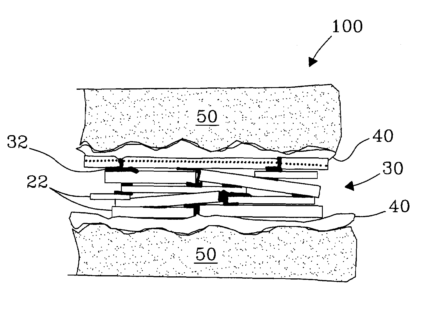
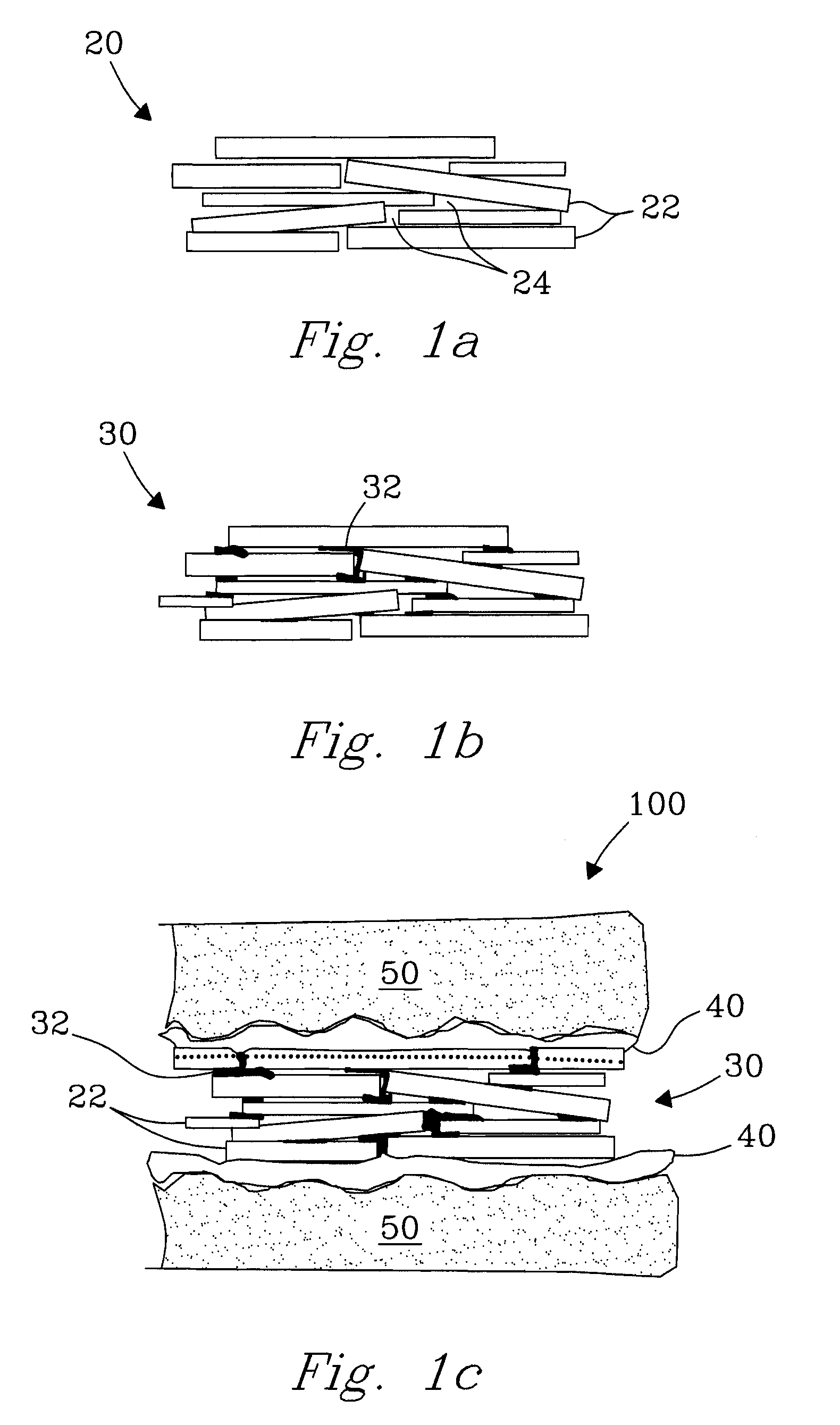
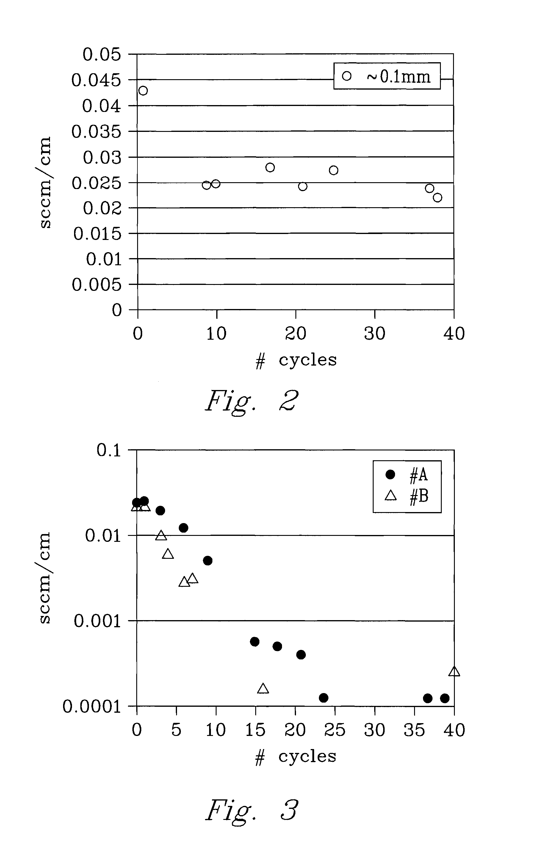
[0027]In one embodiment, the infiltrated sealing (gasket) member 30 was prepared using a liquid infiltration solution comprising at least one glass or melt forming material. The solid glass former was dissolved in an aqueous liquid to a point of saturation, and subsequently delivered into a plurality of spaces 24 (e.g., voids, interstices, flow paths, leak pathways, etc.) within the matrix of the mica substrate 20 using standard liquid delivery techniques (e.g., pipet). Subsequent drying of the substrate 20 fixes the glass or melt former within the matrix, preparing the infiltrated sealing (gasket) member 30 for use. The sealing member 30 was subsequently leak tested in a simulated multilayer compressive seal (hybrid) 100 under a selected compressive stress in the range from 50 to 100 psi under repeated thermal cycling conditions and at expected operating temperatures up to 850° C., and more preferably in the range from 650° C. to 850° C.

Experimental

[0028]Sample A was heat treated a...

example 2

[0035]In a second embodiment of the present invention, infiltration of the sealing member 30 was conducted as described in Example 1 with the substitution of Bi(NO3)3 in a liquid carrier as the infiltrating liquid, as described hereafter.

Experimental

[0036]The infiltrating liquid was prepared by introducing 20-26 g Bi(NO3)3 solid (98% Bi(NO3)3.5H2O, Alfa Aesar, Ward Hill, Mass.) in 50 mL of de-ionized water at room temperature. Formation of subnitrates (due to a more limited solubility of bismuth nitrate) in the aqueous medium was not found to compromise the beneficial infiltrating properties of the bismuth nitrate. Infiltration was subsequently conducted at room temperature, as described in Example 1. Following infiltration, the sealing member 30 was oven dried at 50° C. for between 0.5 and 1 hour to fix the infiltrating (glass forming) material 32 within the substrate of the sealing member 30. Heating of the bismuth nitrate converts it to the oxide form (Bi2O3) which has a melting ...

example 3

[0039]In yet another embodiment of the present invention, an infiltrated sealing (gasket) member 30 was formed, filled, and sealed with a composite material, a preferred material being a mica-glass (G-18) composite. More specifically, mica flakes 22 or particles 22 ranging in size from a few hundred microns to a few mm were premixed with a glass or melt forming material in a liquid carrier (aqueous or organic solvent(s)). An organic solvent(s) as a liquid carrier was preferred for mixing (e.g., MEK) over the aqueous alternative(s) given the excellent mixing in the composite mixture, the rapid evaporation of the solvent(s), and the faster drying times. Mixing was best effected using a ball-mill or comparable mixer. The sealing (gasket) member 30 was subsequently formed, defined, and / or otherwise applied using standard ceramic processing techniques known to those of ordinary skill in the art. Conventional ceramic processing methods include slip casting, tape casting, tape calendaring,...


PUM

PropertyMeasurementUnit
operating temperaturesaaaaaaaaaa
temperatureaaaaaaaaaa

Abstract

A mica based compressive seal has been developed exhibiting superior thermal cycle stability when compared to other compressive seals known in the art. The seal is composed of compliant glass or metal interlayers and a sealing (gasket) member layer composed of mica that is infiltrated with a glass forming material, which effectively reduces leaks within the seal. The compressive seal shows approximately a 100-fold reduction in leak rates compared with previously developed hybrid seals after from 10 to about 40 thermal cycles under a compressive stress of from 50 psi to 100 psi at temperatures in the range from 600° C. to about 850° C.

Description

[0001]This application is a Continuation-In-Part of application Ser. No. 10 / 134,072, filed Apr. 26, 2002 now U.S. Publication No. 2003-0203267A1 published Oct. 30, 2003.[0002]The invention was made with Government support under Contract DE-AC0676RLO 1830, awarded by the U.S. Department of Energy. The Government has certain rights in the invention.FIELD OF THE INVENTION[0003]The present invention relates to an advanced multilayer compressive seal, generally. More particularly, the present invention relates to an advanced mica-based sealing (gasket) member for use in multilayer compressive seals applicable to high-temperature devices and methods of making and using. High-temperature devices include electrochemical devices such as solid oxide fuel cells, syngas generators, and membrane reactors whereby different gaseous streams internal to the device at elevated temperatures must be kept separate from each other. The sealing member and compressive seal of the present invention exhibit ...

Claims


Application Information

Patent Timeline
Patent Type & Authority Patents(United States)
IPC IPC(8): H01M2/00F16J15/08C04B37/02F16J15/10F16J15/12H01M2/08H01M8/02H01M8/12H01M8/24
CPCC04B37/04F16J15/102F16J15/122H01M2/08H01M8/0282H01M8/0286C04B37/025B32B2311/00Y02E60/525C04B2235/3427C04B2235/3445C04B2235/3472C04B2237/062C04B2237/343C04B2237/40C04B2237/408H01M8/0276H01M8/2425H01M8/248H01M2008/1293Y02E60/50Y10S277/943Y02P70/50Y02E60/10
Inventor CHOU, YEONG-SHYUNGSTEVENSON, JEFFRY W.
Owner BATTELLE MEMORIAL INST
Why Eureka
Try Eureka