Methods for processing holes by moving precisely timed laser pulses in circular and spiral trajectories

a laser pulse and circular and spiral technology, applied in the field of lasers, can solve the problems of limited drilling, slow mechanical drilling methods, and prone to tool breakag

Active Publication Date: 2007-08-21
ELECTRO SCI IND INC
View PDF11 Cites 56 Cited by
  • Summary
  • Abstract
  • Description
  • Claims
  • Application Information

AI Technical Summary

Benefits of technology

[0025]1. Preferred tool patterns reduce beam positioner acceleration and jerk problems by approaching hole locations from outside the center of the hole. During the approach movement, a move segment, referred to as a dt / 2 segment, has a duration equal to one-half of the circular segment duration and has zero acceleration. This approach movement results in much less servo error. Because the tool velocity is constrained by the square root of available acceleration, this hole approaching method allows tool velocity to be increased by 41%, unless constrained by other factors. The removal of high acceleration from the dt / 2 segment also allows the maximum circular oscillatory frequency to be increased while maintaining hole drilling quality. The ratio of the dt / 2 segment acceleration to circular acceleration when drilling is defined as a factor α. As α is increased, the initial hole position moves toward the center of the hole, with α=2 representing the prior art startup position. For α=0, the dt / 2 segment has the preferred zero relative acceleration.
[0027]3. The tool patterns can execute spiral and repeated perimeter processing in a single step without turning off laser pulsing.
[0031]7. When the tool patterns are used in a circle-at-perimeter-only mode, no laser pulses are placed inside the perimeter path, which eliminates the prior problems of unevenly distributed laser energy.

Problems solved by technology

Electronic circuitry continues to grow in complexity while simultaneously shrinking in size and cost.
Moreover, mechanical drilling methods have been slow, prone to tool breakage, and limited to drilling so-called “through” holes.
1. Prior tool patterns cause undue acceleration limits on positioner systems. Prior art trepanning entails moving the laser beam in a circular motion around the perimeter of the hole being processed. Skilled workers know that the radial acceleration of circular motion is equal to ν2 / R, where ν is the tool velocity, and R is the radius of the circular motion. After positioning the tool to the center of the hole, trepanning is preceded by an initial move segment that transitions in a smooth manner between the center of the hole and the start of circular motion to limit the tool acceleration and jerk (rate-of-change of acceleration). With prior art trepanning, the acceleration required by the initial move segment is 2ν2 / R, which is twice the acceleration required for the circular motion. Moreover, the motion axis requiring the double acceleration is the same axis executing a half-time duration acceleration pulse, resulting in a jerk profile four-times greater than circular motion requires. The laser beam positioning system acceleration is limited because twice the motor current is demanded at twice the servo frequency.
2. Prior spiral tool patterns are limited to outward spiraling, which limits the types of material that can be processed.
3. Prior trepan and spiral tools require time-wasting multiple steps for processing a hole with both spiral and repeated perimeter motions. Executing multiple steps requires the beam positioner to perform a generic move algorithm that requires at least two acceleration pulses to move the tool back to the center of the hole between steps.
4. If beam positioner settling time is required for recovering from a high acceleration, high velocity move from a prior hole, the settling time is implemented by a constant tool velocity move to the next hole target location, which limits the available beam positioner motion range. This motion range is significant when employing galvanometer-based beam positioners.
5. The above-described settling time technique also fails to settle the beam positioner at the steady state hole processing frequency, which causes a transient motion response when oscillatory circular motion begins.
6. Prior tool patterns are unduly slow when multiple repetitions of a spiral tool are required to approach the hole from various entry angles. Prior beam positioner methods employ the above-described generic move algorithm that requires at least two acceleration pulses to return to the center of the hole between repetitions.
7. Prior trepan tool patterns may cause uneven removal of material. This is so because the laser beam energy is concentrated in one quadrant of the hole as the beam moves from the center of the hole to the perimeter, and back again.
8. Prior spiral and trepan tools do not synchronize the timing of laser triggering signals with beam positioner motion, which causes an omission of a first hole processing pulse because typical Q-switched lasers do not generate a first pulse on command.
9. Prior trepan tool patterns used for drilling holes with multiple repetitions at the perimeter, substantially overlap laser pulses around the hole perimeter, and thereby cause uneven removal of material.

Method used


Image

  • Methods for processing holes by moving precisely timed laser pulses in circular and spiral trajectories
  • Methods for processing holes by moving precisely timed laser pulses in circular and spiral trajectories
  • Methods for processing holes by moving precisely timed laser pulses in circular and spiral trajectories

Examples


Embodiment Construction

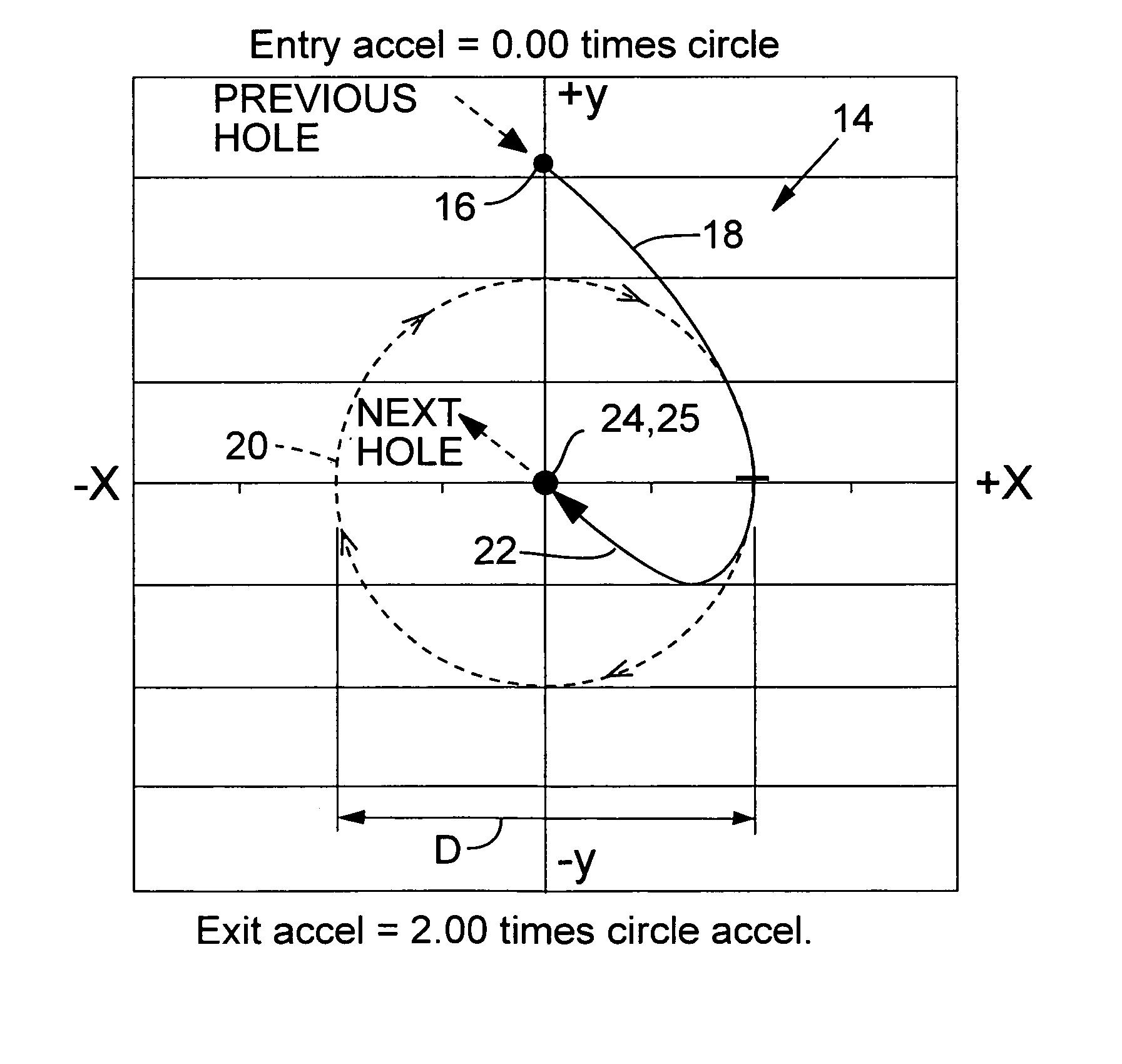
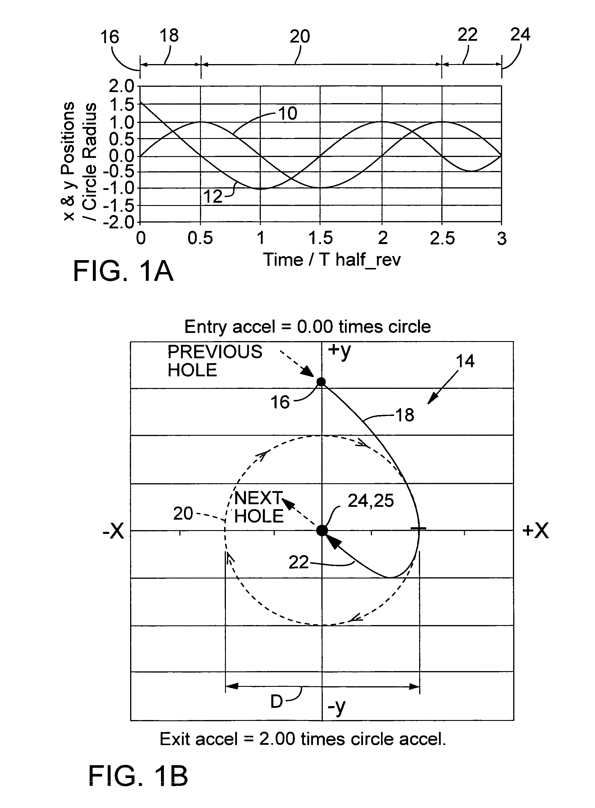
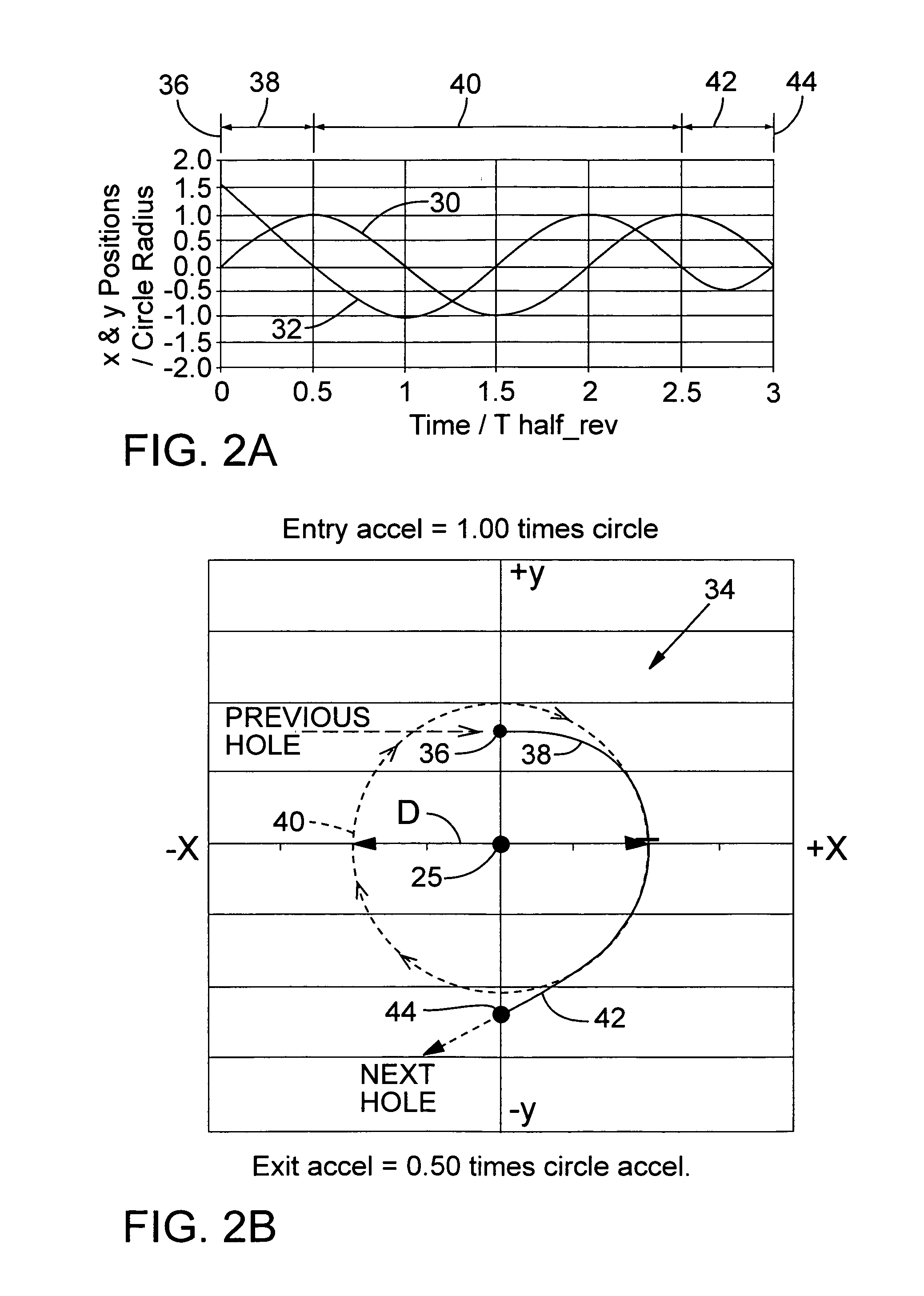
[0053]As mentioned in the background information section, to achieve high-speed, accurate positioning of a laser beam, positioner systems must control jerk, which is the rate of change of acceleration. Many prior positioner systems effected circular motion with a string of short interconnected linear moves. However, the sudden angular change at each interconnection produced unacceptably large jerks that limited speed and positioning accuracy.

[0054]Circular motion is fundamental in hole drilling applications, so employing sinusoidal positioner driving waveforms is preferred. In particular, preferred positioner driving waveforms employ half-sine-shaped acceleration segments that start and stop at a zero acceleration point. Each acceleration segment has a period TMIN that is the shortest non-zero acceleration half-sine segment within the acceleration capability of the positioner system and avoids positioner resonance problems.

[0055]As shown in FIGS. 1A and 2A, circular motion is achiev...


PUM

PropertyMeasurementUnit
distanceaaaaaaaaaa
diameteraaaaaaaaaa
diameteraaaaaaaaaa

Abstract

High speed removal of material from a specimen employs a beam positioner for directing a laser beam axis along various circular and spiral laser tool patterns. A preferred method of material removal entails causing relative movement between the axis of the beam and the specimen, directing the beam axis at an entry segment acceleration and along an entry trajectory to an entry position within the specimen at which laser beam pulse emissions are initiated, moving the beam axis at a circular perimeter acceleration within the specimen to remove material along a circular segment of the specimen, and setting the entry segment acceleration to less than twice the circular perimeter acceleration.

Description

COPYRIGHT NOTICE[0001]© 2004 Electro Scientific Instruments, Inc. A portion of the disclosure of this patent document contains material that is subject to copyright protection. The copyright owner has no objection to the facsimile reproduction by anyone of the patent document or the patent disclosure, as it appears in the Patent and Trademark Office patent file or records, but otherwise reserves all copyright rights whatsoever. 37 CFR § 1.71(d).TECHNICAL FIELD[0002]The technical field relates to lasers and more particularly to methods for employing laser beams to rapidly process holes in various specimen materials.BACKGROUND INFORMATION[0003]Electronic circuitry continues to grow in complexity while simultaneously shrinking in size and cost. The resulting circuit density increase has placed large demands on production throughput of high-density integrated circuits, hybrid circuits, and ECBs.[0004]Prior workers have employed ganged mechanical drills and punches to process holes in EC...

Claims


Application Information

Patent Timeline
Patent Type & Authority Patents(United States)
IPC IPC(8): B23K26/38
CPCB23K26/386H05K3/0026H05K2201/09063B23K26/389B23K26/38
Inventor PAILTHORP, ROBERT M.LEI, WEISHENGMATSUMOTO, HISASHISIMENSON, GLENNWATT, DAVID A.UNRATH, MARK A.JORDENS, WILLIAM J.
Owner ELECTRO SCI IND INC
Why Eureka
Try Eureka