Speed control of brushless DC motors

a brushless dc motor and speed control technology, applied in the direction of motor/generator/converter stopper, dynamo-electric converter control, instruments, etc., can solve the problems of poor efficiency, cumbersome and unreliable commutator and brush structure, linear regulators tend to dissipate significant power loss, etc., to achieve good open-loop speed regulation, reduce noise, reduce nois

Inactive Publication Date: 2007-08-21
GREEN MARK TECH
View PDF3 Cites 63 Cited by
  • Summary
  • Abstract
  • Description
  • Claims
  • Application Information

AI Technical Summary

Benefits of technology

[0022]It is therefore an objective of the present invention to provide an apparatus for controlling the speed of a brushless DC motor, which has a good open-loop speed regulation, and makes the motor running at low speed not stall even if a full load is suddenly applied to it. Moreover, by the apparatus for controlling the speed of a brushless DC motor, the degradation of the starting torque can be eliminated, the high-frequency PWM and associated noise can be mitigated, and the conduction loss or core loss also does not increase.

Problems solved by technology

The BLDC motor omits the cumbersome and unreliable commutator and brush structure of the conventional DC motor.
The main drawback of this conventional motor with a linear regulator is very poor efficiency in that the linear regulator tends to dissipate significant power loss.
However, the conventional motor with PWM speed control has some drawbacks.
If the duty is set too short, for example, 0.5 or lower, the motor will have a low starting torque such that the motor may not start properly with a pre-applied heavy load.
In a situation when the load of the motor fluctuates wildly, such as in a power drill, a sudden application of a heavy load may cause the motor to stall.
Because the shaft torque is smaller than what the actual load demands, the motor will quickly decelerate.
But since the new load torque curve (the heavy load torque curve) does not intersect with the 50% duty line, the motor will stall if the control circuit cannot react in time.
Unfortunately, the Hall sensor will send out exactly 4 step signals (rising and falling edges) per mechanical revolution.
The dilemma is, before an impending stall, the rotating speed of the motor quickly decelerates, but the interval for the Hall sensor to regularly send out the step signal becomes longer.
Moreover, if the applied PWM frequency is too low (<20 kHz), there will be audible switching noise.
On the other hand, if the applying PWM frequency is too high (>20 kHz), there will be extra conduction loss (because the coil's AC resistance is significantly higher at >20 kHz) and higher core loss (because the eddy current loss due to the flux density changes at the higher frequency).

Method used


Image

  • Speed control of brushless DC motors
  • Speed control of brushless DC motors
  • Speed control of brushless DC motors

Examples


Embodiment Construction

[0052]Reference will now be made in detail to the preferred embodiments of the present invention, examples of which are illustrated in the accompanying drawings. Wherever possible, the same reference numbers are used in the drawings and the description to refer to the same or like parts.

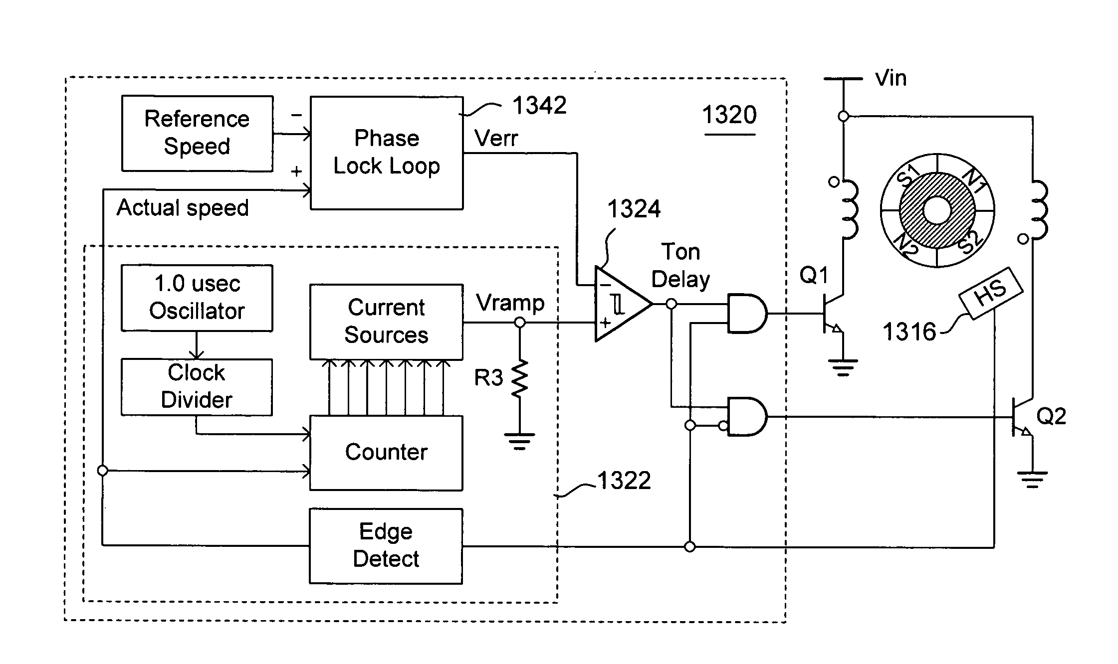
[0053]FIG. 8 is a circuit diagram of one preferred embodiment of the present invention. Brushless DC (BLDC) motor 800 has a rotor 804 disposed within vertical stator poles and horizontal stator poles (not illustrated). The apparatus 810 for controlling the speed of BLDC motor 800 comprises a Hall sensor (HS) 816, a first switch 812, a second switch 814, and a turn-on delay control circuit 820. Hall sensor 816 detects a magnetic rotor section of rotor 804. First switch 812 produces magnetic north on the vertical stator poles and magnetic south on the horizontal stator poles of BLDC motor 800. Second switch 814 produces magnetic south on the vertical stator poles and magnetic north on the horizontal st...


PUM


Abstract

The speed control apparatus comprises a plurality of Hall sensors, a plurality of switches, a turn-on control circuit, and a gate drive logic. The Hall sensors are configured to detect magnetic rotor sections of a poly-phase brushless DC motor at different positions. The switches apply voltages on a plurality of windings to respectively produce magnetic north or south on stator poles of the poly-phase BLDC motor. The turn-on control circuit generates a conduction time reduction after each output transition of the Hall sensors. The gate drive logic separately turns on or turns off the switches according to different output transitions of the Hall sensors to respectively apply voltages on the windings with the conduction time reduction.

Description

BACKGROUND[0001]1. Field of Invention[0002]The present invention relates to brushless DC motors. More particularly, the present invention relates to an apparatus for controlling the speed of the brushless DC motor.[0003]2. Description of Related Art[0004]Brushless DC (BLDC) motors using permanent magnets are simple in design and rugged in structure. The BLDC motor omits the cumbersome and unreliable commutator and brush structure of the conventional DC motor. A dual-phase and 4-pole design of the BLDC motor is especially popular for low-power (less than 100 W) applications. If the performance and speed control of the BLDC motors keeps improving, the BLDC motors have potential to be prevalent in home appliances, air-conditioning, and machine tools, replacing induction motors and brush DC motors.[0005]A 4-pole BLDC motor requires only one low-cost Hall sensor to operate the motor properly. FIG. 1 illustrates a schematic view of a typical 2-coil, 4-pole BLDC motor design. The armature ...

Claims


Application Information

Patent Timeline
Patent Type & Authority Patents(United States)
IPC IPC(8): H02P1/18
CPCH02P6/205Y10S388/911H02P6/21
Inventor LIU, KWANG-HWA
Owner GREEN MARK TECH
Why Eureka
Try Eureka