Porous microsphere resonators

a microsphere and resonator technology, applied in the field of optical devices, can solve problems such as lowering detection limits, and achieve the effect of increasing material amount and increasing optical interaction

Inactive Publication Date: 2007-08-21
3M INNOVATIVE PROPERTIES CO
View PDF48 Cites 26 Cited by
  • Summary
  • Abstract
  • Description
  • Claims
  • Application Information

AI Technical Summary

Benefits of technology

[0004]There exist different applications where it is desirable to increase the amount of material that is to be introduced to the surface of a microresonator. The use of a porous surface permits greater amounts of the material to be captured on or near the surface of the microresonator, resulting in an increased optical interaction between the material and the light propagating within the microresonator. Accordingly, part of the invention is directed to the inclusion of a porous material at least on the surface of the microresonator.

Problems solved by technology

Despite the high sensitivity associated with microresonator-based sensors, there remains a need to further increase the sensitivity of such devices, thus lowering the detection limit.

Method used


Image

  • Porous microsphere resonators
  • Porous microsphere resonators
  • Porous microsphere resonators

Examples


example 1

Porous Layer

[0041]A sol-gel approach is used in which pore forming agents such as surfactants are included for forming a porous layer over a core. This permits control of the pore sizes that can provide some size discrimination, for example, unimodal pores with a diameter in the range of about 2 to about 50 nm diameter, with diameter control <10%. When Stober spheres are used, the diameter range is from about 2 nm to 1000 nm or more.

[0042]A simple system involves combining tetraethoxysilane, nonionic surfactant, acid, water, and ethanol to form a coating solution. This solution can be applied to the core spheres by dipping or spraying. The surfactant can be removed if desired by liquid extraction or heating. The walls of the pores can be functionalized via silane coupling agents.

example 2

Porous Layer

[0043]Surfactant-templated silica films were dip-coated onto microsphere resonators and onto silicon substrates. The resonators and the silicon substrates were calcined at 400° C. for 15 minutes to remove the surfactant and leave nanometer diameter unimodal pores. Porosities of the films range from ˜25 to ˜50 volume percent, and refractive indices range from 1.21–1.34.

[0044]In this example, there are, by design, two sets of four samples (eight conditions). One set has film thicknesses that range from 40–55 nm; the second set has film thicknesses that range from 230–280 nm. Silica concentration in the coating solution is the key factor used to control thickness. Each set of four samples has two samples with small (˜3 nm) and two samples with large (˜10 nm) pore diameters. Surfactant formula weight is used to control pore diameter. Note that the pore diameters in both sets are much smaller than the wavelength of the probe light (>400 nm). It is anticipated that these porou...

example 3

Experimental Results Using Porous Microresonators

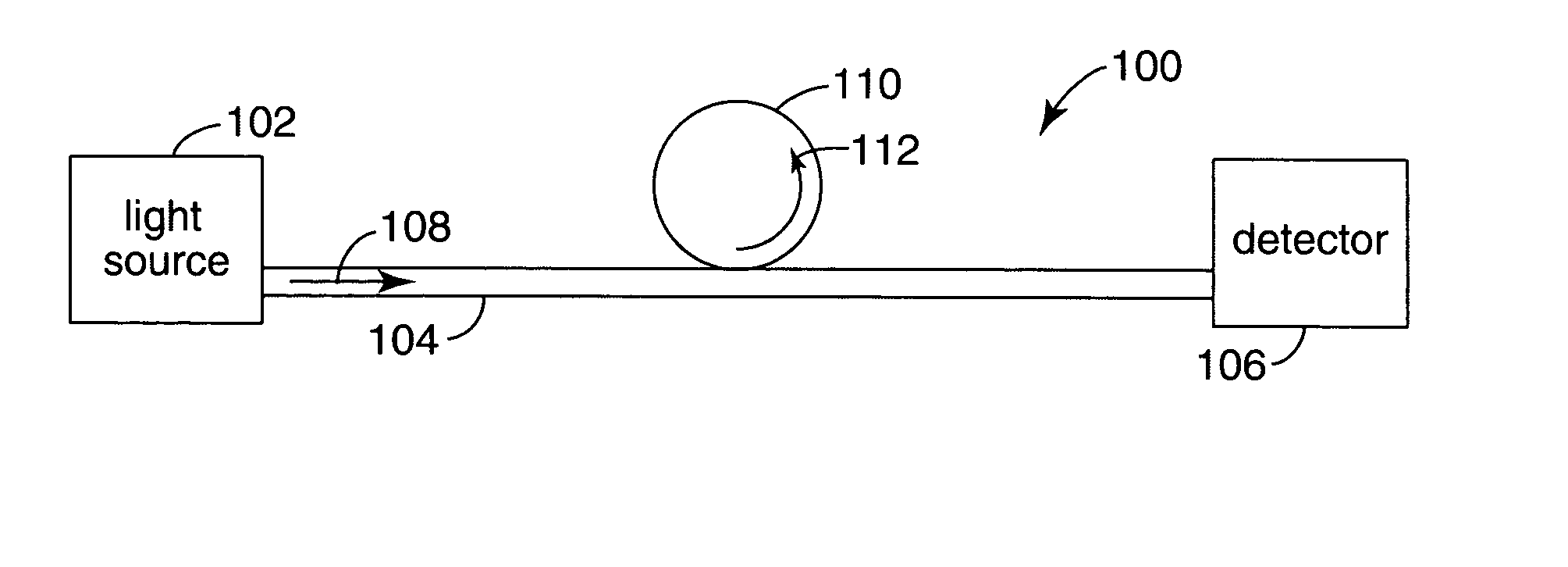
[0062]Experiments were carried out to determine the effective Q-factors of microresonators fabricated according to the procedure outlined in Example 2. The experimental arrangement was similar to that shown in FIG. 1A. In each experiment, a fiber 108 was placed in contact with the microresonator 110 and both were immersed in water. A tunable diode laser (Velocity 6304 from New Focus) was used as light source 102 with the wavelength centered at around 630 nm. The wavelength of the light emitted by the laser was tuned by varying the voltage that drives a piezo-actuator inside the laser. When the wavelength was on-resonance with one or more of the whispering gallery modes 112 of the microresonator, the amount of laser power coupled into the microresonator was increased, leading to a power drop at the detector 106.

[0063]FIG. 7 shows the detected signal at the detector as a function of laser tuning, where the microresonator was formed acco...


PUM

PropertyMeasurementUnit
porosityaaaaaaaaaa
sizeaaaaaaaaaa
sizeaaaaaaaaaa

Abstract

There are several different applications where it is desirable to increase the amount of material that can be introduced to the surface of a microresonator that has whispering gallery modes. The use of a porous surface on the microresonator permits greater amounts of the material to be captured on or near the surface of the microresonator, resulting in an increased optical interaction between the material and the light propagating in the whispering gallery mode(s) of the microresonator.

Description

FIELD OF THE INVENTION [0001]The present invention is directed generally to optical devices, and more particularly to optical devices based on microresonators.BACKGROUND [0002]Dielectric microspheres or planar waveguide ring- or disk-shaped resonators have attracted increasing attention in sensing applications, including biosensing. The size of these types of resonators typically ranges from approximately 20 μm to a few millimeters for microspheres and from 5 μm to a few tens of microns for ring- or disk-shaped resonators. Such microspheres and ring- or disk-shaped resonators are often referred to as microresonators. In the most common configuration in microresonator-based biosensors, a microresonator is placed in a close proximity to an optical waveguide such as optical fiber whose geometry has been specifically tailored, for example tapered or etched to a size of 1–5 μm.[0003]The tapering modifications to the waveguide result in there being a substantial optical field outside the ...

Claims


Application Information

Patent Timeline
Patent Type & Authority Patents(United States)
IPC IPC(8): G01N21/59G01N21/77G02B6/12
CPCG01N21/7746G02B2006/12138
Inventor FAN, XUDONGANDERSON, MARK T.SCHARDT, CRAIG R.
Owner 3M INNOVATIVE PROPERTIES CO
Why Eureka
Try Eureka