Low-coherence interferometry optical sensor using a single wedge polarization readout interferometer

a low-coherence interferometry and optical sensor technology, applied in the direction of thermometers, instruments, convert sensor outputs, etc., can solve the problems of not being able to use standard measurement tools, the measurement suffers from a 2 phase ambiguity, and the optical sensor aimed at industrial applications and other non-laboratory type applications is likely to be exposed to severe environmental conditions. , to achieve the effect of simple and robust optical

Active Publication Date: 2007-08-21
OPSENS
View PDF3 Cites 57 Cited by
  • Summary
  • Abstract
  • Description
  • Claims
  • Application Information

AI Technical Summary

Benefits of technology

[0013]The invention provides a simple and robust optical sensor system aimed at industrial and other applications and based on low-coherence interferometry using the tandem interferometer arrangement, for measuring a physical quantity such as, but not limited to, the temperature, the pressure, the strain, the displacement.

Problems solved by technology

When using a narrowband light source, the coherence length of the source is generally greater than the path length difference of the interferometer and therefore the measurement suffers from a 2π phase ambiguity, due to the periodic nature of the interferogram fringes, which may severally restricts the measuring applications.
Optical sensing systems based on LCI and aimed to industrial applications and to other non-laboratory type applications have also emerged as commercial products but they are still not standard measurement tools and there are just a few number of commercial suppliers.
The optical sensors aimed at industrial applications and other non-laboratory type applications are likely to be exposed to severe environmental conditions.
These industrial “must-have” requirements adding to economic constraints prevented many optical sensing technologies developed in the laboratories from reaching the industrial sensor and other non-laboratory marketplaces.
Their optical sensing system is based on narrow-band light source so their measuring technique suffers from the 2π phase ambiguity and therefore offers a limited measurement range.
Since the resulted signal is obtained in the frequency or wavelength domain rather than in the time or spatial domain, they use a Discrete Fourier Transform signal processing method which can be time consuming without mentioning the cost and complexity of using a dispersive spectrometer configuration.
Moreover, the above-mentioned crystals are known to have a strong frequency-dependence of their birefringence which can severally reduce the accuracy of the Fourier transform signal-processing method.
The Fizeau interferometer, although it has no moving part, is made of an air-spaced wedge or a solid optical wedge which is not easy to produce as it requires the use of very complex thin film deposition methods or the use of optical component manufacture and assembly methods with severe thickness tolerances, optical alignment, material stability and optical quality.
These types of configurations produce complex assembly devices and suffer from important drawbacks.
However, the inclination of the plane of localization produces a residual focusing error at the surface of the photodetector and therefore leads to a reduction in the fringe contrast unless the light source has a high degree of spatial coherence.
To prevent this situation, Lequime proposes some modifications in their configuration by using a second Wollaston prism and an achromatic halfwave plate, but at the expense of increasing the complexity of the device.
Such solution is likely to increase the sensitivity of the readout interferometer to environmental influences and therefore is not desired for industrial-based applications.
Another solution proposed is to use a light source with narrower spectrum where the dispersion effect can be neglected but this solution comes to the expense of widening the path length difference region of the fringes which reduce the accuracy of the envelope peak or fringe peak location.

Method used


Image

  • Low-coherence interferometry optical sensor using a single wedge polarization readout interferometer
  • Low-coherence interferometry optical sensor using a single wedge polarization readout interferometer
  • Low-coherence interferometry optical sensor using a single wedge polarization readout interferometer

Examples


Embodiment Construction

[0047]In the following description of the embodiments, references to the accompanying drawings are by way of illustration of an example by which the invention may be practiced. It will be understood that other embodiments may be made without departing from the scope of the invention disclosed.

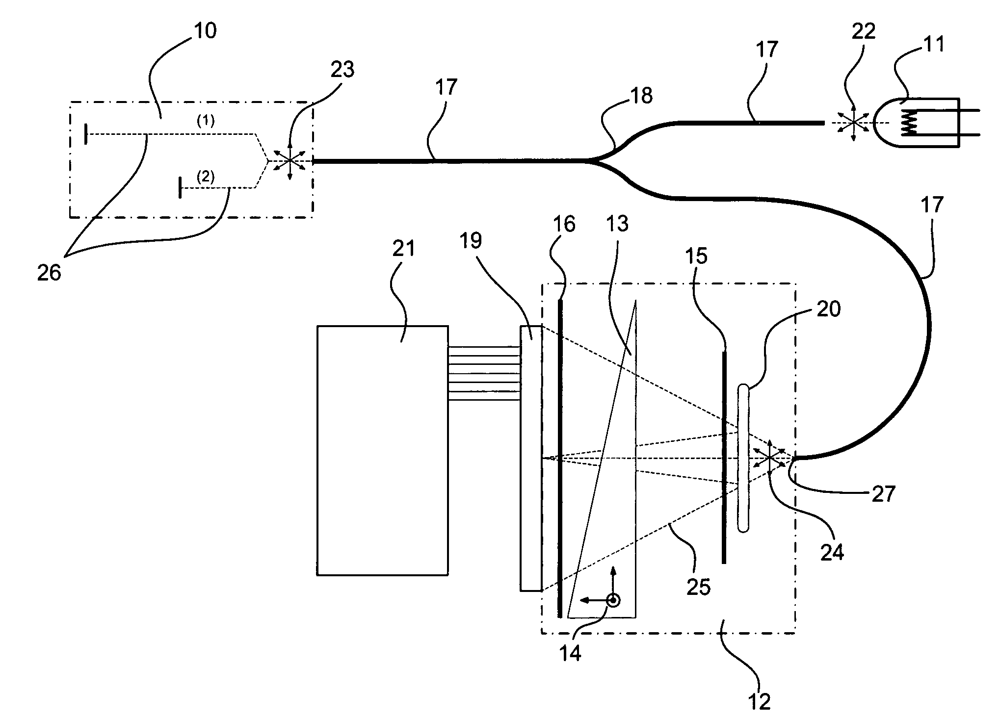
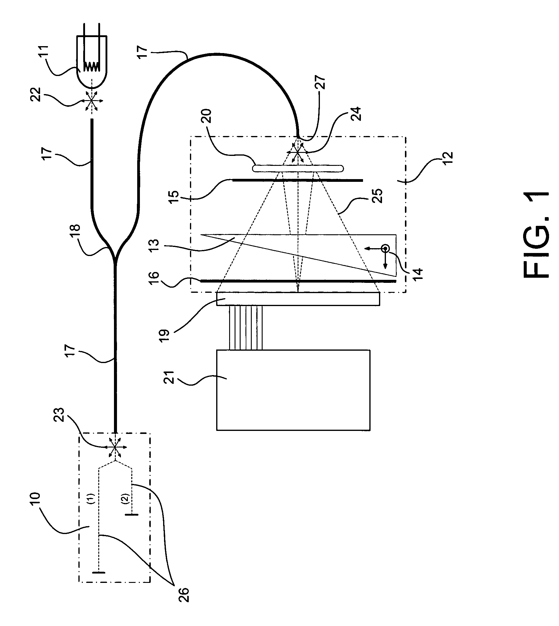
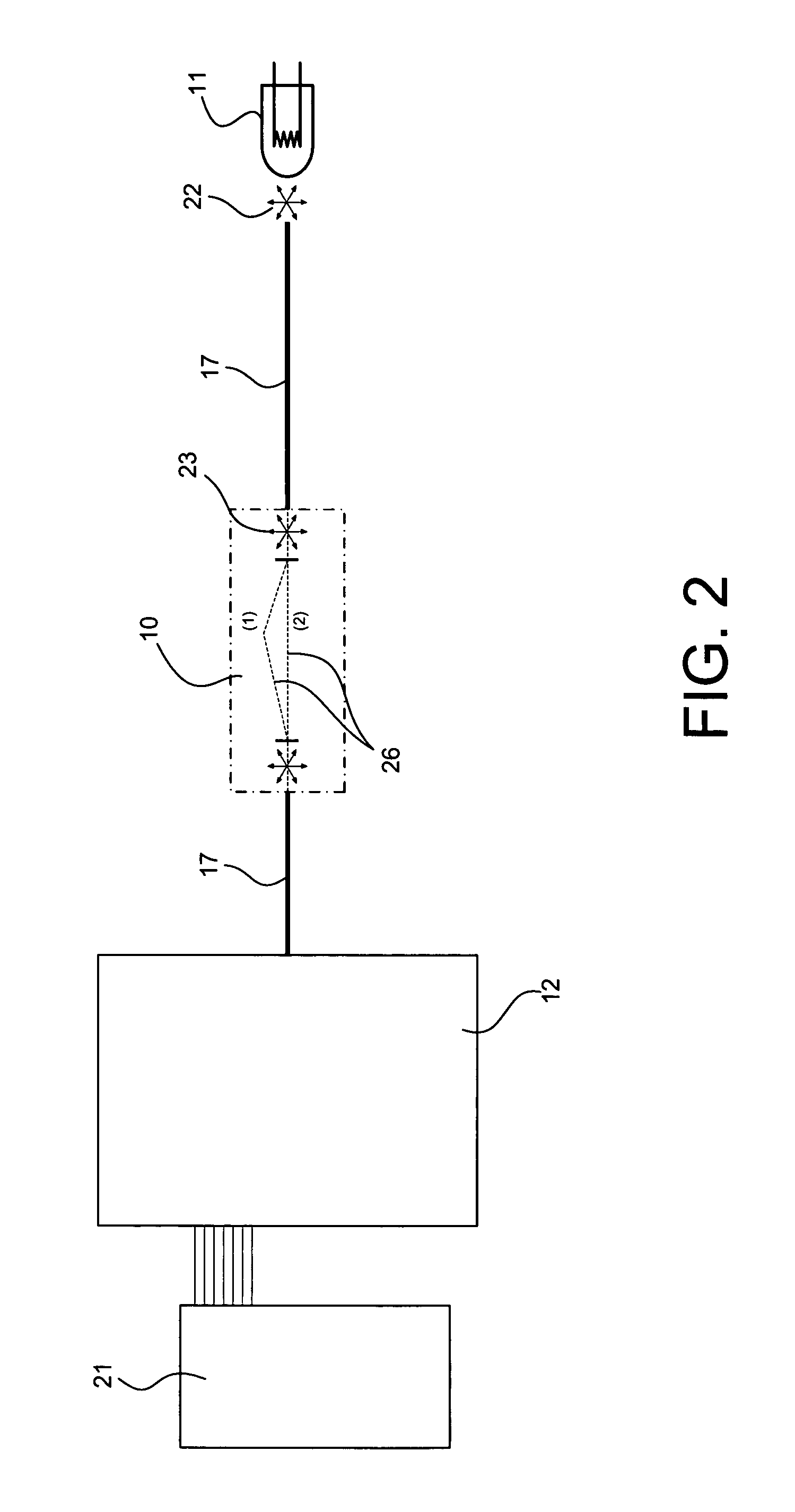
[0048]There are two basic configurations for the tandem interferometer optical sensor arrangement, which are the reflective and transmissive configurations. The optical sensor of the reflective configuration showed in FIG. 1 comprises a sensing interferometer 10 used in reflection mode and having its path length difference sensitive to the measured physical quantity. Preferably, the interferometer is a two-beam 26 interferometer, or a good approximation of this type of interferometer such as low finesse Fabry-Perot interferometer. A set of optical fibers 17 and an optical coupler 18 connect the sensing interferometer 10 to the light source 11 and to the readout interferometer 12. Light 22 emitt...


PUM


Abstract

The invention provides a method and a system for measuring a physical quantity by means of a tandem interferometer optical sensor system based on low-coherence interferometry. The system comprises a light system, a sensing interferometer and a polarization readout interferometer. The invention provides a polarization interferometer comprising a single birefringent wedge. The invention also provides for a dispersion-compensated optical sensor system. The invention also provides an interferometer sensitive to temperature that comprises a trajectory in a LiB3O5 crystal with an x-cut orientation.

Description

CROSS-REFERENCE TO RELATED APPLICATIONS[0001]This application claims priority under 35USC§120 of U.S. provisional patent application 60 / 610,950, filed on Sep. 20, 2004, the specification of which is hereby incorporated by reference.FIELD OF THE INVENTION[0002]This invention relates to an optical sensor based on low-coherence interferometry (LCI) for measuring a physical quantity. In particular, it relates to a LCI-based optical sensor based on the tandem interferometer arrangement with a polarization readout interferometer.BACKGROUND OF THE ART[0003]The interferometer is known as a very accurate optical measurement tool for measuring a physical quantity by means of the measurand-induced changes of the interferometer path length difference. When using a narrowband light source, the coherence length of the source is generally greater than the path length difference of the interferometer and therefore the measurement suffers from a 2π phase ambiguity, due to the periodic nature of the ...

Claims


Application Information

Patent Timeline
Patent Type & Authority Patents(United States)
IPC IPC(8): G01B9/02
CPCG01D5/266G01K11/00G01K11/3206G01B9/0209G01B9/02065G01B9/02023G01B9/02032G01B9/02028G01J2009/0292G01B2290/70
Inventor DUPLAIN, GAETAN
Owner OPSENS
Why Eureka
Try Eureka