
Strain detector and method of manufacturing the same

a technology of strain detector and strain gauge, which is applied in the direction of force/torque/work measurement apparatus, screws, instruments, etc., can solve the problems of weakening the juncture between the diaphragm and the strain gauge of the resistance wire, limited availability of the strain detector disclosed in the document, and poor mechanical strength and corrosion resistance. , to achieve the effect of high precision and reliability in measurement, excellent mechanical strength and corrosion resistan

Active Publication Date: 2007-09-04
NAGANO KEIKI
View PDF21 Cites 3 Cited by
  • Summary
  • Abstract
  • Description
  • Claims
  • Application Information

AI Technical Summary

Benefits of technology

The present invention provides a strain detector with high precision and reliability using an austenitic precipitation hardening type Fe—Ni heat-resisting steel strain generating body and an insulating film made of silicon oxide. The strain detector is excellent in mechanical strength, corrosion resistance, and can measure stress of acidic gases and highly corrosive materials. The insulating film is adjusted to the internal stress to prevent degradation of the strain generating body and the junction between the strain generating body and the insulating film is not degraded even after long-term use. The strain detector is easy to manufacture and can be used for measuring stress in environments exposed to hydrogen gas or embrittlement. The strain detector is also excellent in measuring the stress of highly corrosive materials.

Problems solved by technology

However, although this martensitic precipitation hardening type stainless steel is excellent in the mechanical strength, the corrosion resistance is not so high, and therefore availability of the strain detector disclosed in the document is limited especially when measuring the pressure of fluids such as highly corrosive acidic gases, chemical agents, or hydrogen gas which causes embrittlement, or the like.
Further, when the thin wall portion with smaller thickness is formed by using a material having the high tensile strength such as the martensitic precipitation hardening type stainless steel in the diaphragm, the thin wall portion can generate large strain, but the glass material used for jointing the thin wall portion and the resistance wire strain gauge receives a large stress from the thin wall portion.
When a strain detector made by using the aforesaid adhesive in the aforesaid diaphragm portion is used for a long time, juncture between the diaphragm and the resistance wire strain gauge becomes weaker, and strain of the diaphragm can not accurately be detected as an electric signal, namely a highly reliable measured pressure value can no longer be obtained.
Further, since the strain detector requires the work for adhering a plurality of resistance strain gauges discretely with an adhesive, manufacture of the strain detector takes a long period of time and much labor load, which are also disadvantageous.
The problems as described above are not limited to the field of strain detectors for measuring the pressure a fluid, and also other general strain detectors have the same problems

Method used


Image

  • Strain detector and method of manufacturing the same
  • Strain detector and method of manufacturing the same
  • Strain detector and method of manufacturing the same

Examples


first embodiment

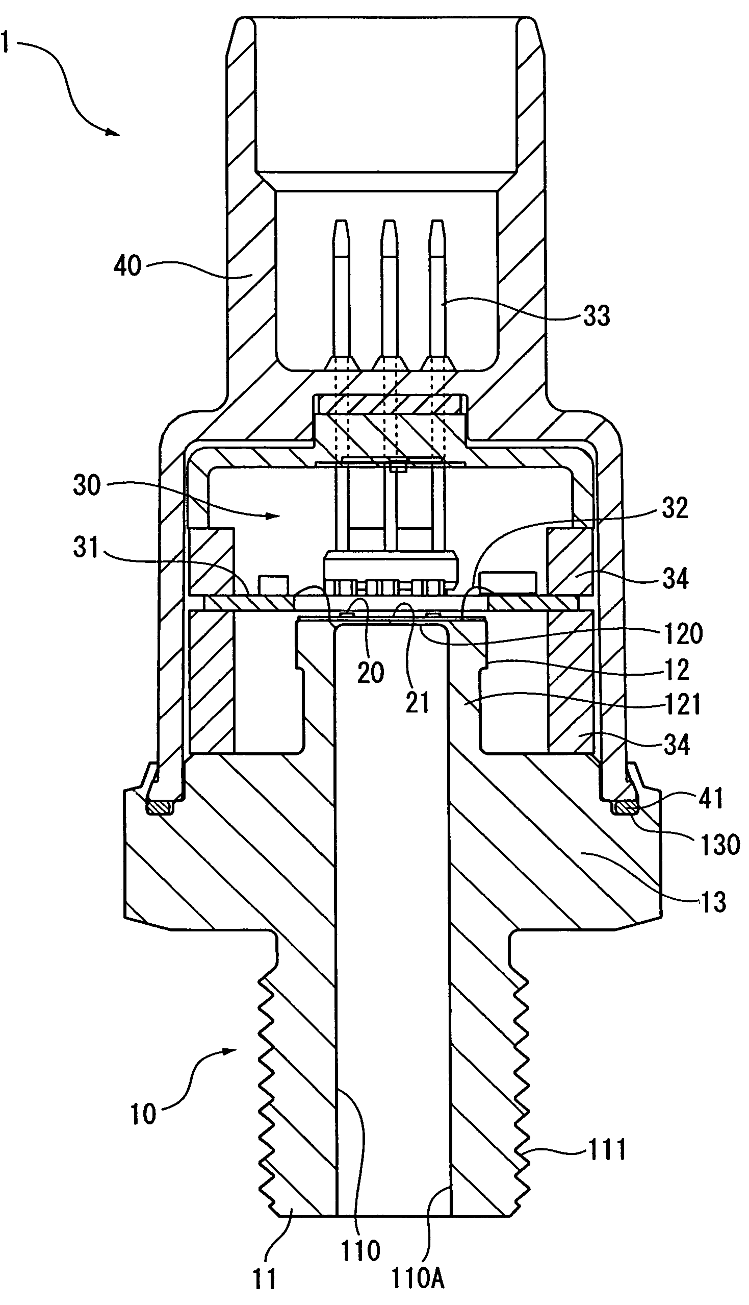
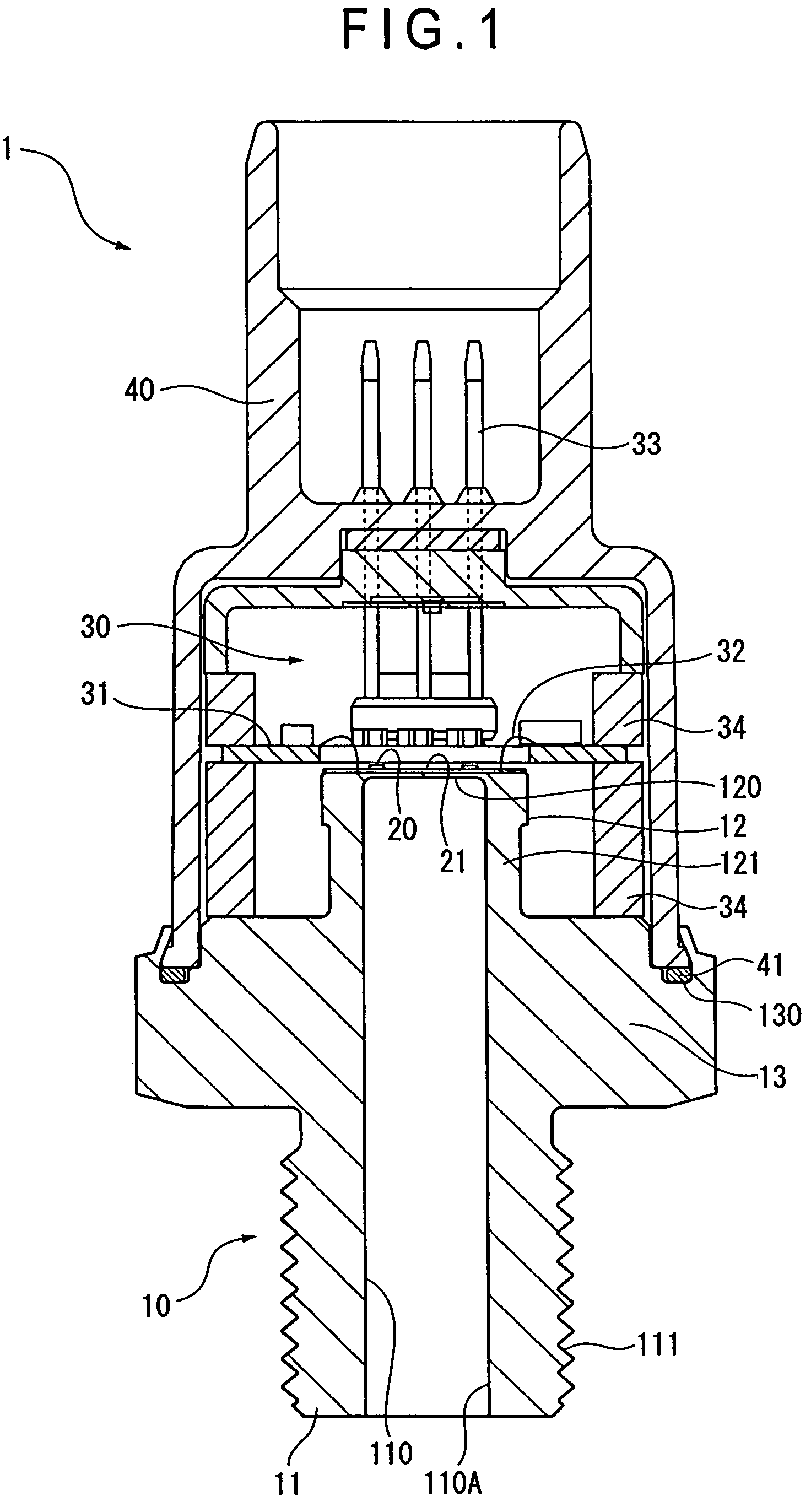
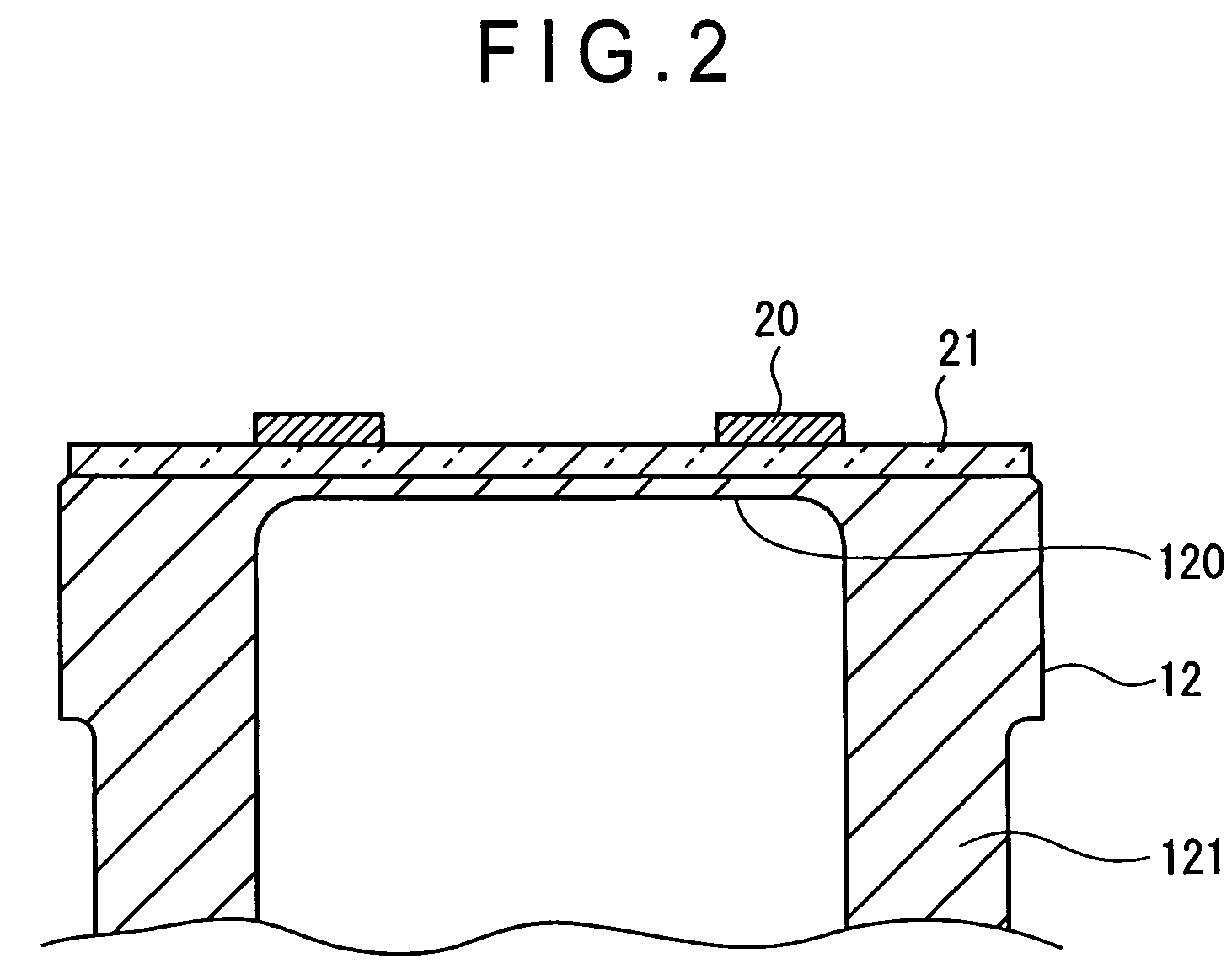
[0027]A first embodiment of the present invention is described with reference to the related drawings. FIG. 1 is a cross-sectional view showing a fluid pressure sensor 1 according to the first embodiment of the present invention. FIG. 2 is a cross-sectional view showing a primary portion of the fluid pressure sensor according to the embodiment above in the enlarged state. This fluid pressure sensor 1 can be used for measuring the pressure of various types of fluids such as gases, liquids, and the like flowing in piping, and especially for measuring the pressure of fluids such as highly corrosive acidic gases or chemical agents, or hydrogen gas which causes embrittlement. In FIG. 1, the fluid pressure sensor 1 comprises a pressure introducing joint 10, a strain gauge 20, a circuit section 30, and a housing 40.

[Configuration of the Pressure Introducing Joint 10]

[0028]The pressure introducing joint 10 is integrally formed including a joint member 11 having a substantially cylindrical s...

second embodiment

[0068]Descriptions are provided below for a second embodiment of the present invention with reference to the related drawings. FIG. 6A and FIG. 6B are views each showing a strain detector 50 according to the second embodiment of the present invention, and FIG. 6A is a flat view showing the strain detector 50, while FIG. 6B is a front view showing the same. In this strain detector 50, when a load is applied to a tip section of a cantilever strain generating body 51, the strain generating body 51 is deflected, and the strain is detected as an electric signal by a strain gauge 53 to measure the load. This strain detector may be used, for instance, as a scale.

[0069]In FIG. 6A and FIG. 6B, the strain detector 50 has the cantilever strain generating body 51, a silicon oxide film 52 which is an insulating layer, and a strain gauge 53. The strain generating body 51 is a block body having a substantially rectangular shape with the prespecified thickness, and a base edge thereof is fixed to a...


PUM

PropertyMeasurementUnit
thicknessaaaaaaaaaa
tensile strengthaaaaaaaaaa
temperatureaaaaaaaaaa

Abstract

A fluid pressure sensor (1) for measuring the pressure of a fluid comprises a diaphragm portion (12) which is a strain generating body, a silicon oxide film (21) as an insulating film, and a strain gauge (20) made of crystalline silicon, and austenitic precipitation hardening type Fe—Ni heat-resisting steel excellent in mechanical strength and corrosion resistance is used for the diaphragm portion (12). The silicon oxide film (21) is formed with the internal stress thereof adjusted to the range from −150 to 130 MPa. With this feature, the fluid pressure sensor (1) ensures high precision and reliability, and may be used even for measurement of a highly corrosive fluid.

Description

BACKGROUND OF THE INVENTION[0001]1. Field of the Invention[0002]The present invention relates to a strain detector for measuring an external stress by converting strain generated in a strain generating body to an electric signal, and a method of manufacturing the same.[0003]2. Description of Related Art[0004]There have been developed various types of strain detectors for measuring an external stress using a strain generating body in which a component is strained according to an external stress, and a strain gauge for converting a strain of the strain generating body to an electric signal. For instance, in a strain detector currently available for measuring the pressure of a fluid such as a gas or a liquid, a strain generating body is strained by the pressure of a fluid, and the strain is converted to an electric signal indicating the pressure of the fluid.[0005]As the strain detector for measuring the pressure of a fluid, there have been known, for instance, a strain detector disclo...

Claims


Application Information

Patent Timeline
Patent Type & Authority Patents(United States)
IPC IPC(8): G01B7/16
CPCG01L9/0051G01L9/0055F02M2200/24
Inventor NAGASAKA, HIROSHIABE, TAKESHIKANEKO, YOSHIKAZU
Owner NAGANO KEIKI
Learn More