
Power unit having crankcase to which auxiliary machine is fitted, and motorcycle having power unit

a technology of auxiliary machines and power units, which is applied in the direction of mechanical equipment, machines/engines, auxilaries, etc., can solve the problems of troublesome oil pump fitting work, deterioration of rigidity of crankcases, so as to reduce the size of the crankcase around the crank shaft, improve the working efficiency of auxiliary machines, and reduce the size of the crankcas

Active Publication Date: 2007-09-11
HONDA MOTOR CO LTD
View PDF2 Cites 1 Cited by
  • Summary
  • Abstract
  • Description
  • Claims
  • Application Information

AI Technical Summary

Benefits of technology

This approach enhances the efficiency of fitting the auxiliary machine, reduces the size of the crankcase, and allows for increased banking angle and exhaust pipe arrangement latitude in motorcycles.

Problems solved by technology

When the oil pump is fitted to the crankcase with the driven sprocket fitted to the drive shaft of the oil pump, first the endless chain wound around the drive sprocket should be wound around the driven sprocket and then, while keeping this condition, the oil pump should be fitted to the crankcase with bolts or the like, so oil pump fitting work is troublesome.
In this case, if all the driven sprocket is exposed inside the opening when viewed from the axial direction of the crank shaft, it would be easy to fit the driven sprocket to the drive shaft but the opening should be large enough, so the rigidity of the crankcase would deteriorate.
Furthermore, if the endless chain which drives the oil pump is wound around the drive sprocket which is fitted to the crank shaft, there should be space for the endless chain between the crank shaft and the oil pump drive shaft and thus the size of the crankcase should be large around the crank shaft and also the opening should be large, so the rigidity of the crankcase would deteriorate.

Method used


Image

  • Power unit having crankcase to which auxiliary machine is fitted, and motorcycle having power unit
  • Power unit having crankcase to which auxiliary machine is fitted, and motorcycle having power unit
  • Power unit having crankcase to which auxiliary machine is fitted, and motorcycle having power unit

Examples


Embodiment Construction

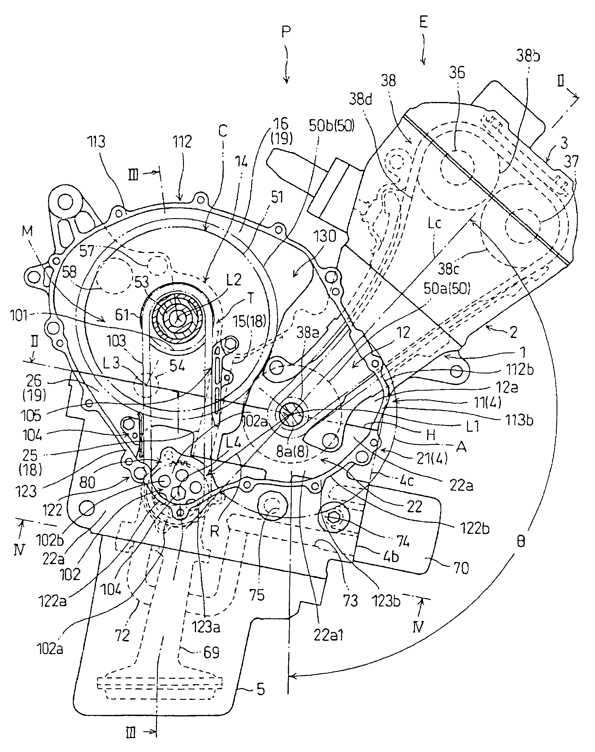
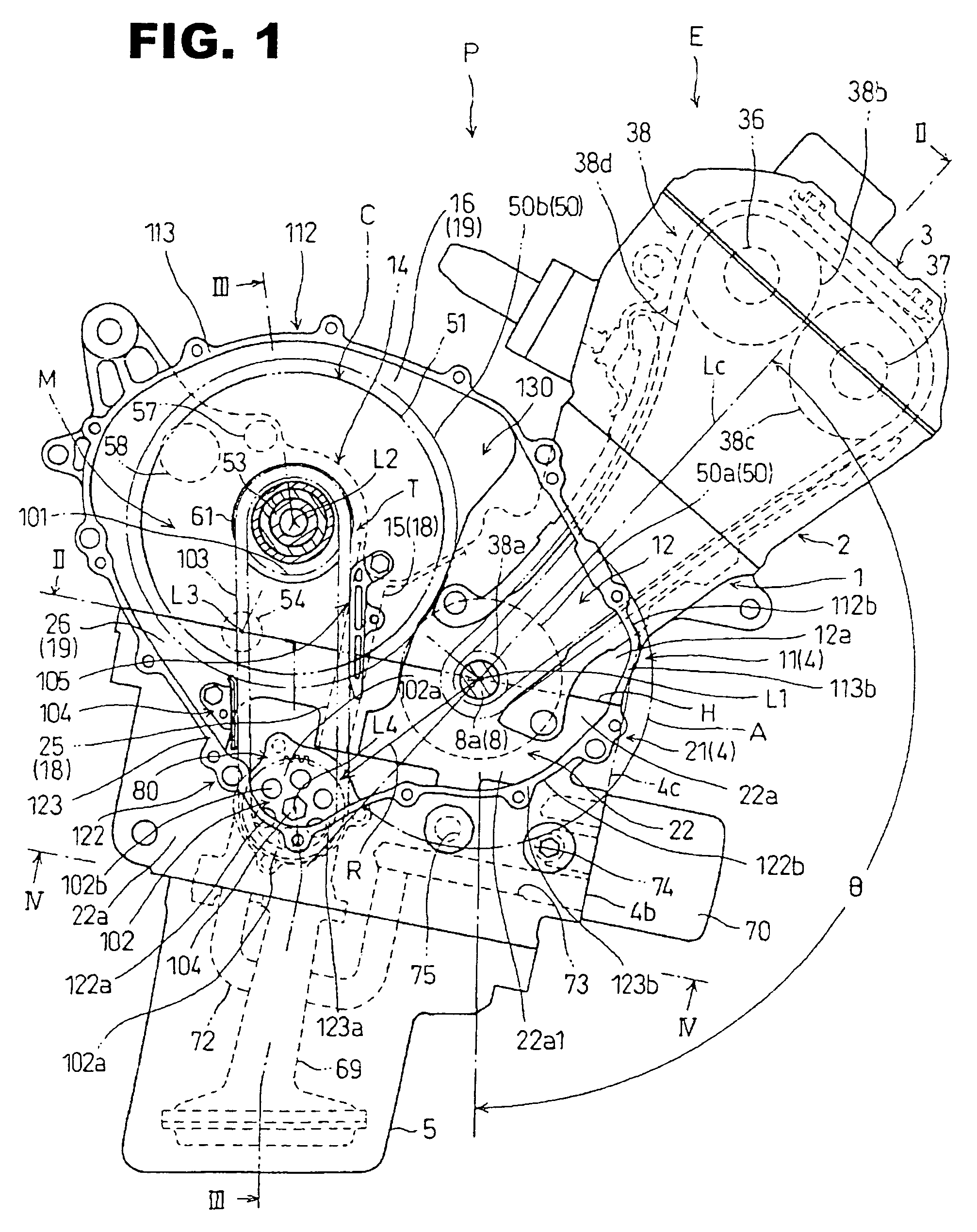
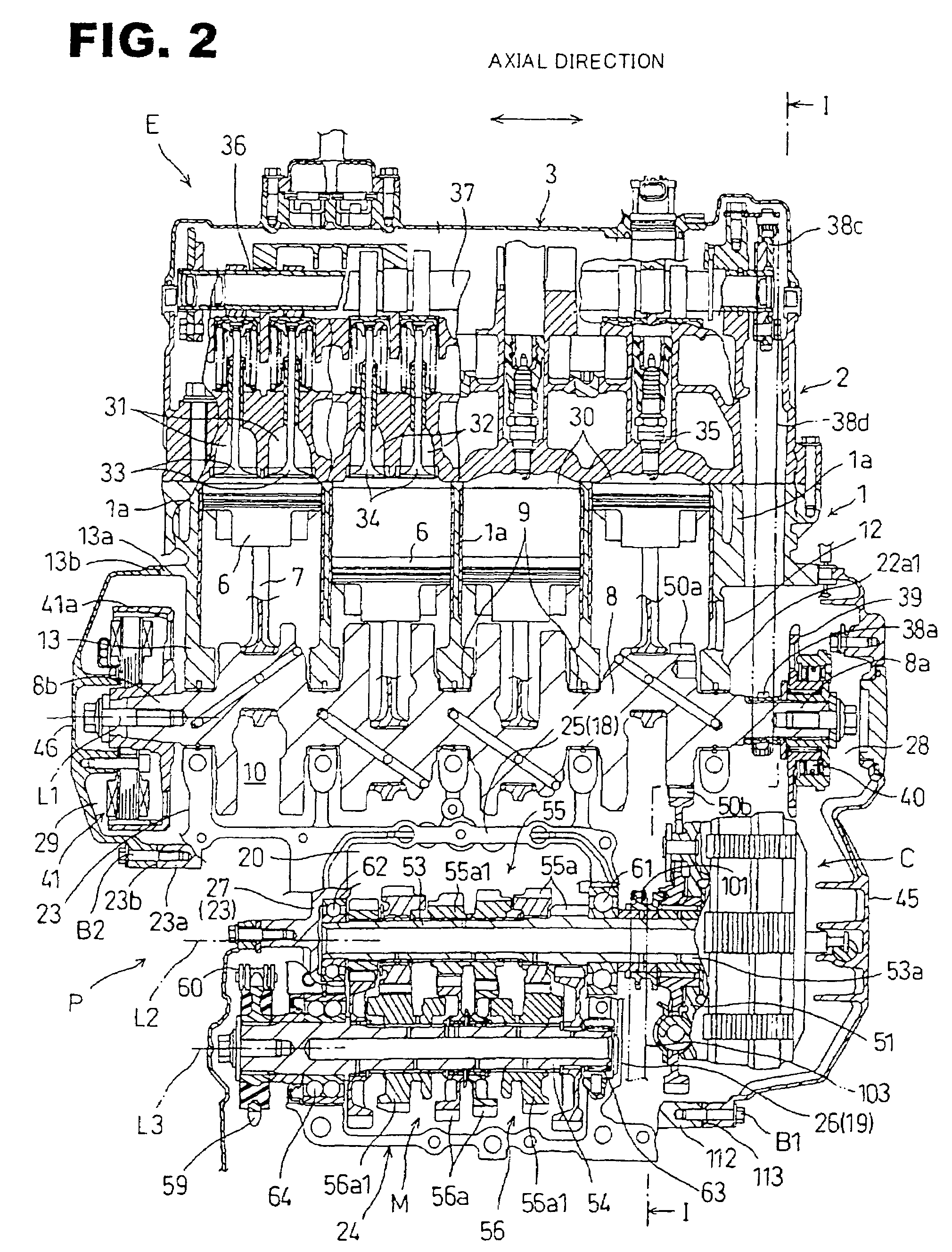
[0027]Referring to FIGS. 1 and 2, a power unit P to which the present invention is applied is to be mounted on a motorcycle as a vehicle and includes a water-cooled multicylinder 4-stroke internal combustion engine E and a power transmission system which transmits power generated by the internal combustion engine E to a rear wheel as a driving wheel, and the power transmission system includes a multiple-disc friction clutch C as a clutch and a constant-mesh type gear transmission M as a transmission.

[0028]The internal combustion engine E, which is to be mounted on a motorcycle with a rotational centerline L1 of a crank shaft 8 transversely oriented and horizontal, has an engine body which includes: a cylinder block 1 as an integral molding of four cylinders 1a arranged serially, a cylinder head 2 joined to the top end of the cylinder block 1, a head cover 3 joined to the top end of the cylinder head 2, a lower crankcase 21 joined to the bottom end of the cylinder block 1, and an oil...


PUM


Abstract

An internal combustion engine in a power unit includes an oil pump that rotates by a transmission mechanism with an endless chain, and a crankcase with an opening formed by protruding walls of side walls of the crankcase in an axial direction. A drive sprocket is fitted to a main shaft of a gear transmission and a driven sprocket is fitted to a shaft end of a drive shaft of an oil pump. When viewed sideways, the protruding walls and mating faces have overlapping parts that partially overlap the driven sprocket. On the other hand, all the shaft end and the remainder of the driven sprocket are exposed inside the opening when the cover is removed. The resulting configuration improves the working efficiency in fitting an oil pump into the crankcase without reducing the rigidity of the crankcase.

Description

CROSS-REFERENCE TO RELATED APPLICATION[0001]The present application claims priority under 35 U.S.C. §119 to Japanese Patent Application No. 2005-285801, filed Sep. 30, 2005, the entire contents of which are hereby incorporated by reference.BACKGROUND OF THE INVENTION[0002]1. Field of the Invention[0003]The present invention relates to a power unit with an internal combustion engine having an auxiliary machine rotated by a transmission mechanism and a crankcase which houses the transmission mechanism and the auxiliary machine and to which the auxiliary machine is fitted, and a motorcycle which has the power unit.[0004]2. Description of Background Art[0005]It has been known that an oil pump of an internal combustion engine is housed in a space formed by a crankcase (for example, see JP-A No. 2004-143952 ). In the case where the oil pump is rotated by a transmission mechanism with an endless chain, a driven sprocket with the endless chain wound around it is fitted to the drive shaft of...

Claims


Application Information

Patent Timeline
Patent Type & Authority Patents(United States)
IPC IPC(8): F01M1/02F01P5/10F02B61/04
CPCF02B67/06F02B61/02F02B2275/08F02F7/0073F02F2007/0078
Inventor TAKAHASHI, ISAMUTAWARADA, YUICHI
Owner HONDA MOTOR CO LTD
Learn More