
Method of reinforcing an embedded cylindrical pipe

a technology of reinforcing pipes and cylindrical pipes, applied in the direction of pipe laying and repair, mechanical equipment, building repairs, etc., can solve the problems of not being designed to carry pressure, process can then accelerate, and exposed to corrosion risk, etc., to reduce the contamination of the liner through external agents, reduce the risk of corrosion, and reduce the effect of negative moments

Active Publication Date: 2007-09-11
FREYSSINET INT STUP
View PDF20 Cites 7 Cited by
  • Summary
  • Abstract
  • Description
  • Claims
  • Application Information

AI Technical Summary

Benefits of technology

"The present invention provides a method for reinforcing embedded cylindrical pipes using a composite structural reinforcement applied through in situ stratification of reinforcement fibers and resin matrix. The helicoidal layout allows for easy implementation and avoids problems of watertight connection. The band can be mainly composed of carbon fibers with well-established qualities as reinforcement fibers. The composite reinforcement has low porosity but remains relatively high in comparison with metal liners. The composite reinforcement can be adhered directly to the liner or through drainage holes in the liner. The invention also includes a method for reinforcing an underground pipe using a composite structural reinforcement."

Problems solved by technology

The latter is not designed, however, to carry the stress in terms of pressure due to the fluid flowing through.
They are exposed to a risk of corrosion according to the aggressiveness of the environment.
The process can then accelerate and lead to the breaking of the pipe.
Repairs carried out from the inside are generally more expensive.
Such repairs are carried out when the excavation works are impossible or difficult.
One difficulty is that a local error in realization can lead to infiltrations of water in the injected interstice.
This water penetration can cause the concrete core of the pipe to be brought under pressure and can make the new resistant liner inefficient.
This will result in a risk of a break in the pipe outside of the new liner.
When repairing from the inside the reinforcements added cannot be pre-stressed.
When the pipe is brought under pressure these reinforcements undergo a certain elastic deformation (increase in their diameter) which causes cracking of the concrete of the core of the pipe.
It worsens the flexural strength of the pipe and hence its capacity to resist dissymmetrical thrusts of the earth.
This risks causing early corrosion of the new reinforcement if it is metal.

Method used


Image

  • Method of reinforcing an embedded cylindrical pipe
  • Method of reinforcing an embedded cylindrical pipe

Examples


Embodiment Construction

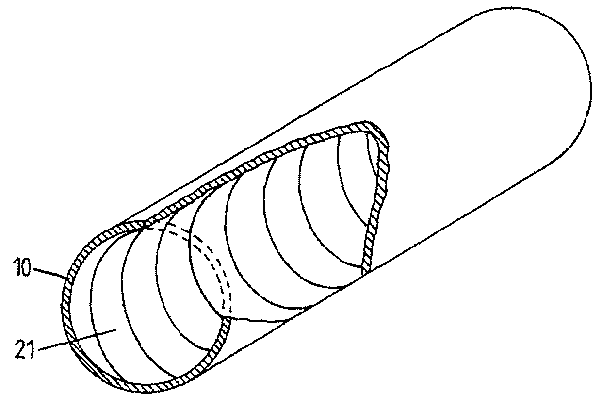
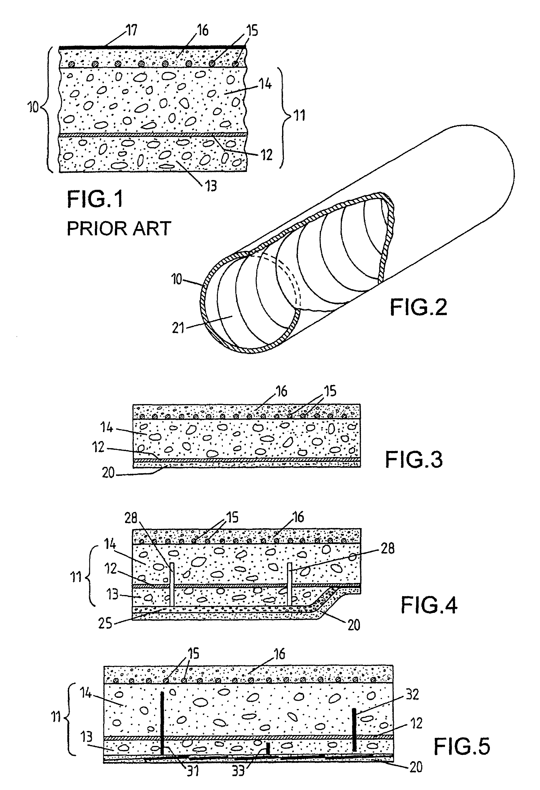
[0034]Referring to the figures, a composite reinforcement 20 is arranged inside a damaged underground pipe. This reinforcement is composed of a band of fibers 21 wound according to a helicoidal path along the internal side of the pipe, as illustrated by FIG. 2 (in which the ground material surrounding the pipe is not shown).

[0035]The pipes in question are preferably embedded cylinder pipes as described previously with reference to FIG. 1. Their diameter is sufficient to allow the intervention of a human operator inside, for example 1.5 to 4.5 m. The service pressure in the pipe can be up to around 0.5 MPa.

[0036]The reinforcement fibers of the band 21 are made from a resistant material (resistance to breaking typically greater than 1500 MPa) and are of a high elastic module (typically between 100 and 400 GPa). Carbon fibers will generally be used for this (resistance to breaking in the range of 3000 MPa). By way of example the bands 21 have a width of 600 mm and they are composed of ...


PUM


Abstract

A composite structural reinforcement is realized within the pipe through in situ stratification of at least one band of reinforcement fibers and a resin matrix. The band is arranged according to a helicoidal path along the internal side of the pipe.

Description

CROSS-REFERENCE TO RELATED APPLICATION[0001]This is a convention utility application derived from and corresponding to French Patent Application Serial No. 04 04833 filed May 5, 2004 having the same title, incorporated herewith by reference and for which priority is claimed.BACKGROUND OF THE INVENTION[0002]In a principal aspect the present invention relates to a methods of reinforcing pipes and in particular repairing embedded pipes.[0003]These pipes belong for example to a water delivery network. In their most common form these pipes are constituted by an end to end assembly of segments of pipe made from pre-stressed concrete and having a relatively large diameter of typically 0.5 m to 6 m environ. Water flows through said pipes under a pressure of up to around twenty bars. These segments of concrete pipe can incorporate an interior metal cylinder (liner). The latter is not designed, however, to carry the stress in terms of pressure due to the fluid flowing through. This stress is ...

Claims


Application Information

Patent Timeline
Patent Type & Authority Patents(United States)
IPC IPC(8): F16L55/18E02D37/00F16L9/08F16L9/153F16L55/165F16L57/00F16L58/16
CPCF16L9/153F16L55/1655F16L55/18
Inventor LECINQ, BENO TSTUBLER, JEROMETOURNEUR, CHRISTIANZIVANOVIC, IVICA
Owner FREYSSINET INT STUP
Learn More