Exposure apparatus and device fabrication method using the same

a technology of exposure apparatus and fabrication method, which is applied in the field of extreme, can solve the problems of reducing resolution, hindering high-quality exposure, and limited resolution of lithography using ultraviolet light, and achieve the effect of increasing the cover angle or size, without lowering throughpu

Inactive Publication Date: 2007-09-25
CANON KK
View PDF12 Cites 14 Cited by
  • Summary
  • Abstract
  • Description
  • Claims
  • Application Information

AI Technical Summary

Benefits of technology

[0016]Accordingly, it is an exemplified object of the present invention to provide an exposure apparatus and device fabrication method using the same, which uses an ellipsoidal mirror as a condenser mirror to condense the EUV light into one point, increases its cover angle or size, and prevents the laser beam that goes straight ahead beyond a target from damaging optical elements including the ellipsoidal mirror for high-quality exposure without lowering the throughput.
[0020]The exposure apparatus may further include a mechanism for three-dimensionally inclining the optical-axis direction of the excitation laser relative to an optical-axis direction of the illumination light. The exposure apparatus may further include a light-shielding member that prevents the excitation laser from reaching the illumination optical system beyond the target. The exposure apparatus may further include a debris removal member that prevents debris that is generated at an emission point of the plasma from reaching the illumination optical system. The exposure apparatus may further include a light-shielding member that prevents the excitation laser from reaching the illumination optical system beyond the target, the light-shielding member having transmittance of about 10% or less to the excitation laser, and a debris removal member that prevents debris that is generated at an emission point of the plasma from reaching the illumination optical system, the debris removal member having transmittance of about 90% or higher to the excitation laser. The light-shielding member may include a metal member and an antireflective coating on the metal member.

Problems solved by technology

However, as the semiconductor device has rapidly become finer, the lithography using the UV light has a limited resolution.
When the excitation laser that crosses the emission point goes straight ahead and reaches the illumination optical system, it thermally deforms the first and subsequent mirrors or thermally destroys the multilayer on the mirror, lowering the resolution and hindering high-quality exposure.
A repair and replacement of the mirror remarkably lowers the working efficiency of the apparatus since the illumination and projection optical systems are housed in a vacuum chamber.
It is conceivable to considerably decrease a beam diameter of the laser light such that the excitation laser falls within the target even when it offsets slightly, but this undesirably decreases the power of the EUV light and lowers the throughput.
Therefore, the conventional debris filter has been insufficient to shield the laser beam that goes straight ahead beyond the EUV emission point.
However, this exposure apparatus restricts the cover angle of the condenser mirror so as to maintain the introduction space of the excitation laser to the target, and does not sufficiently high emission efficiency of the EUV light.
The prior art does not teach a large cover angle of the condenser ellipsoidal mirror, directions of the excitation laser incident onto a target and exiting the target, or interference between the excitation laser and the illumination system including the ellipsoidal mirror.

Method used


Image

  • Exposure apparatus and device fabrication method using the same
  • Exposure apparatus and device fabrication method using the same
  • Exposure apparatus and device fabrication method using the same

Examples


first embodiment

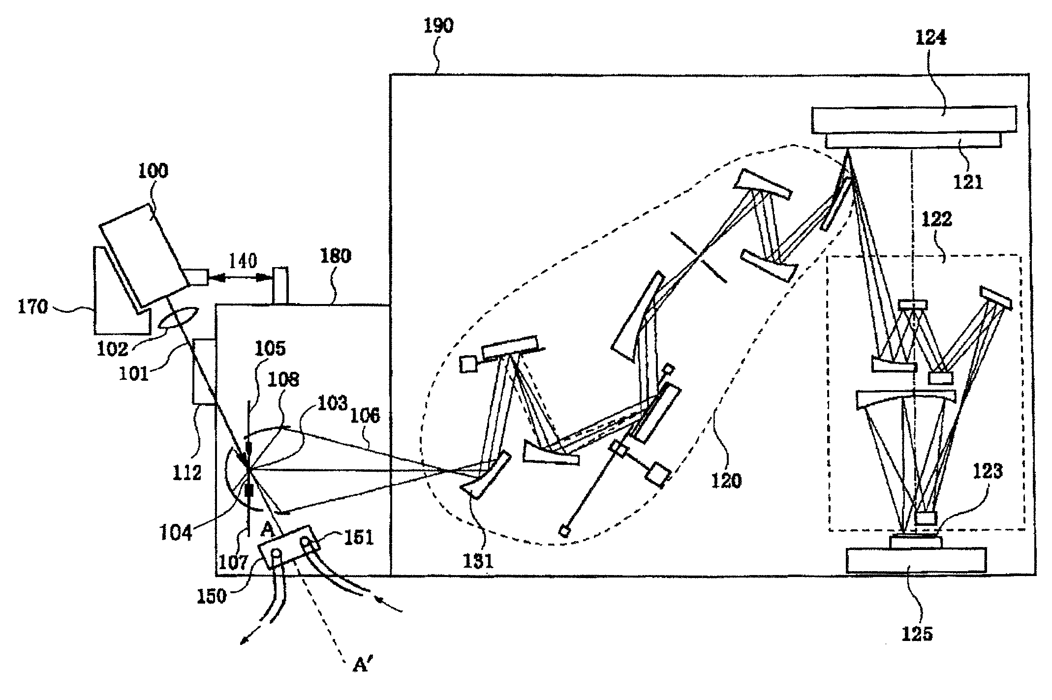
[0038]A description will now be given of an EUV exposure apparatus of a first embodiment according to the present invention, with reference to FIG. 1. FIG. 1 is a schematic plane view of the EUV exposure apparatus. The inventive exposure apparatus is an exposure apparatus that uses EUV light having a wavelength between 10 and 15 nm smaller than that of the UV light (e.g., with a wavelength of 13.5 nm) as exposure light for scan-type exposure.

[0039]Referring to FIG. 1, the exposure apparatus includes a laser plasma light source part, an illumination optical system 120, a catoptric reticle 121, a projection optical system 122, a reticle stage 124, a wafer 123, and a wafer stage 125, and accommodates the illumination optical system 120 to the wafer stage 125 in the vacuum chamber 190.

[0040]The laser plasma light source of the instant embodiment irradiates a highly intensified pulse laser beam 101 from a laser light source 100 through a condenser optical system 102 to a target 104 suppl...

second embodiment

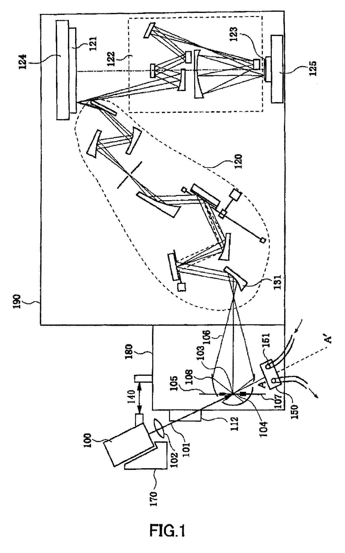
[0070]Referring now to FIG. 2, a description will be given of the second embodiment according to the present invention. Those elements in FIG. 2 which are the same as corresponding elements in FIG. 1 are designated by the same reference numerals, and a description thereof will be omitted. In the instant embodiment, the optical-axis direction AA′ of the laser beam 101 is offset from the optical-axis direction 109 of the EUV light 106 that is generated at the condensing point 103 and incident upon the first mirror 131, such that the EUV light does not interfere with other components including the condenser ellipsoidal mirror 108. In particular, the pulse laser that has been emitted from the target is designed to pass the opening in the condenser ellipsoidal mirror, through which the condensed EUV light passes. Moreover, the condenser ellipsoidal mirror is equipped with the passage part, through which the pulse laser beam that enters the target passes. In this case, the number of passa...

third embodiment

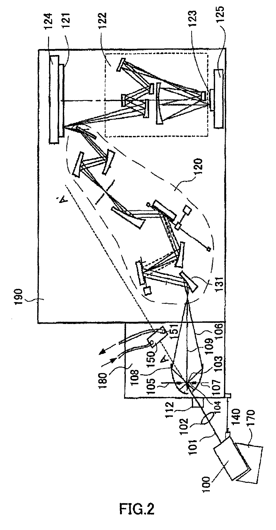
[0074]Referring now to FIG. 3, a description will be given of a third embodiment according to the present invention. This embodiment inclines the laser light source 100 in a direction reverse to that in FIG. 2, and arranges the stopper 150 outside the vacuum chambers 180 and 190. Therefore, the vacuum chamber 180 or 190 is provided with a window 152 to deliver the pulse laser beam 101. The window 152 is preferably made of materials such as quarts that has high transmittance to the pulse laser beam 101. Since the stopper 150 is installed in the air, and thus more easily handled than the vacuum environment from a viewpoint of the thermal process.


PUM

PropertyMeasurementUnit
wavelengthaaaaaaaaaa

Abstract

An exposure apparatus that irradiates excitation laser onto a target, and generates from generated plasma a light source for generating illumination light of an extreme ultraviolet region or an X-ray region includes an illumination optical system that uses the illumination light to illuminate a catoptric reticle that forms a pattern to be transferred, the illumination optical system including a first mirror closest to the light source, an ellipsoidal mirror for condensing the illumination light in front of the first mirror in the illumination optical system, and a projection optical system that reduces and projects the pattern reflected on the reticle onto an object to be exposed, wherein light where an optical-axis direction of the excitation laser proceeds beyond a position that generates the plasma by the excitation laser does not interfere with components in the exposure apparatus including the illumination and projection optical systems, and the ellipsoidal mirror.

Description

[0001]This application claims the right of priority based on Japanese Patent Applications Nos. 2002-127343, filed on Apr. 26, 2002, and 2003-73637, filed on Mar. 18, 2003, which are hereby incorporated by reference herein in their entirety as if fully set forth herein.TECHNICAL FIELD[0002]The present invention relates generally to exposure apparatuses and device fabrication methods, and more particularly to an extreme ultraviolet (“EUV”) exposure apparatus used for a lithography process for manufacturing devices, e.g., semiconductor devices, such as ICs and LSIs, liquid crystal devices, image-pickup devices, such as CCDs, and magnetic heads.BACKGROUND ART[0003]Along with recent demands for smaller and lower profile electronic devices, finer semiconductor devices to be mounted onto these electronic devices have been increasingly demanded. Conventionally, a lithography method for manufacturing a semiconductor device has used a reduction projection exposure using ultraviolet (“UV”) lig...

Claims


Application Information

Patent Timeline
Patent Type & Authority Patents(United States)
IPC IPC(8): G03B27/54G03B27/42G02B17/06G03F7/20G21K5/10H01L21/027H05H1/24
CPCB82Y10/00G02B17/0663G03F7/70033H05H1/24G03F7/70916G03F7/70941H05G2/001G03F7/70175G03F1/24
Inventor HIURA, MITSURUTSUJI, TOSHIHIKO
Owner CANON KK
Why Eureka
Try Eureka