
Wireless instrumentation system and power management scheme therefore

a technology of instrumentation system and power management scheme, which is applied in the direction of repeater circuit, wireless commuication service, high-level techniques, etc., can solve the problems of not being able to communicate consistently, if at all, with the central station, and achieve the effect of increasing the distance capability, effective power, and maximum data transfer

Inactive Publication Date: 2007-09-25
NAT AERONAUTICS & SPACE ADMINISTATION U S GOVERMENT AS REPRESENTED BY THE ADMINISTATOR OF
View PDF19 Cites 37 Cited by
  • Summary
  • Abstract
  • Description
  • Claims
  • Application Information

AI Technical Summary

Benefits of technology

[0007]To address the forgoing needs, the present invention provides a wireless instrumentation system that enables a plurality of low power wireless transceivers to transmit measurement data from a plurality of remote station sensors to a central data collection station accurately and reliably. The system is designed specifically to insure that sensor data can be received from the low power transceivers, even when the transceivers are affected by poor RF signal conditions or no RF signal due to physical placement outside the normal range of the central data collection station. In addition, a unique power management scheme is employed to minimize power usage at each remote station and thereby maximize battery life.
[0013]The wireless instrumentation system also preferably employs an effective power management algorithm to achieve maximum data transfer with minimum power consumption. As noted before, the central station acts as a master station that repeatedly sends the commands to the remote stations until a response is received or timeout occurs. To save power, the remote stations remain in a low power consumption mode much of the time, but are powered up periodically to check whether a central station request for action is received. If so, the power management algorithm will maintain the power to the various circuit elements in the remote station until a reply has been transmitted back to the central station. Once this occurs, the algorithm powers the remote station back down until the arrival of the next time interval for checking for incoming commands from the central station. The power on / off duty cycle implemented by the algorithm can be readily adjusted either by the remote station controller itself or by the central station controller to allow for faster or slower communications, depending on the criticality of the particular parameter being monitored.
[0014]Preferably, the wireless system also employs a modular architecture in which a wireless core module and a power module are common for every remote station. An analog signal conditioning board is provided that is unique to each sensor. The modular design allows for only the analog board to be replaced if a special measurement must be accommodated, thus simplifying the installation for new measurements by requiring minimal hardware changes. Since the system does not require permanent power and communication cables, it becomes easily portable and reconfigurable. The modular architecture also allows for the inclusion of unique functions in the system. Examples of these functions are additional local data storage, local complex data processing, etc.

Problems solved by technology

Mainly because of their low RF power properties, distant stations or those located in signal-poor areas where the communication drop rate is too high, may not be able to communicate consistently, if at all, with the central station.

Method used


Image

  • Wireless instrumentation system and power management scheme therefore
  • Wireless instrumentation system and power management scheme therefore
  • Wireless instrumentation system and power management scheme therefore

Examples


Embodiment Construction

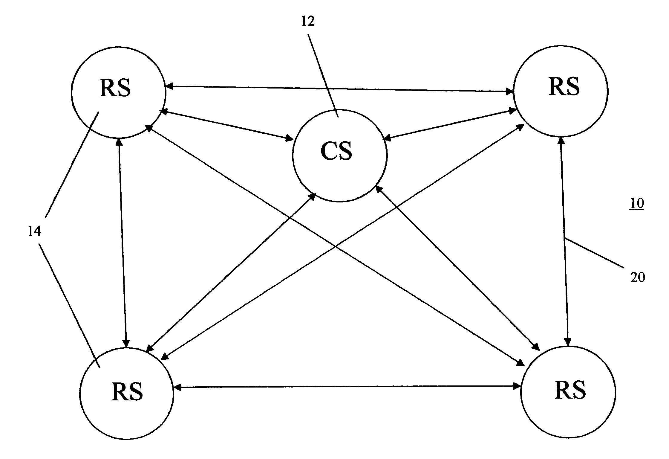
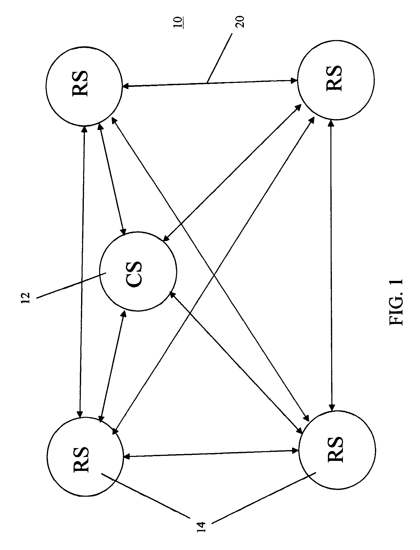
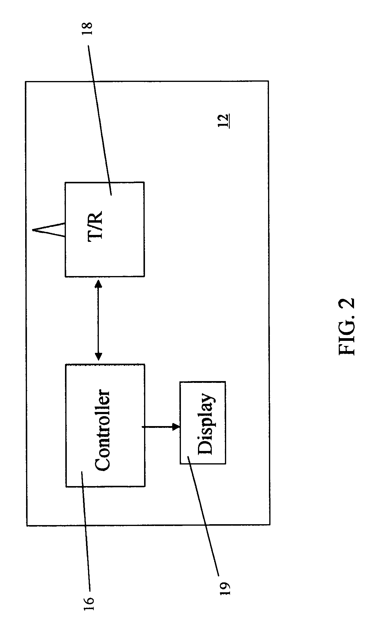
[0023]With reference to FIGS. 1 and 2, a wireless instrumentation system 10 is illustrated that can be configured to operate in accordance with a preferred embodiment of the present invention. The system 10 is in the form of a network and consists of a central station (CS) 12 and one or more remote stations (RS's) 14. It should be noted that the system 10 represents a simple example of the type of communication system with which the concepts of the present invention can be employed, but other more complicated systems that employ more than one central station, for example, could be used as well. The CS 12 is the main controller of the system 10 in that the CS 12 manages all communications with the RS's 14. To provide this functionality, the CS 12 employs a computer based controller 16 and one or more radio frequency (RF) transceivers 18. The controller 16 can be implemented with any suitable processor, single board computer, personal computer, etc. and contains the software required ...


PUM


Abstract

A wireless instrumentation system enables a plurality of low power wireless transceivers to transmit measurement data from a plurality of remote station sensors to a central data station accurately and reliably. The system employs a relay based communications scheme where remote stations that cannot communicate directly with the central station due to interference, poor signal strength, etc., are instructed to communicate with other of the remote stations that act as relays to the central station. A unique power management scheme is also employed to minimize power usage at each remote station and thereby maximize battery life. Each of the remote stations preferably employs a modular design to facilitate easy reconfiguration of the stations as required.

Description

ORIGIN OF THE INVENTION[0001]The invention described herein was made in the performance of work under a NASA contract and by an employee of the United States Government and is subject to the provisions of Public Law 96-517 (35 U.S.C. §202) and may be manufactured and used by or for the Government for governmental purposes without the payment of any royalties thereon or therefore. In accordance with 35 U.S.C. §202, the contractor elected not to retain title.BACKGROUND OF THE INVENTION[0002]1. Field of the Invention[0003]The present invention relates to a wireless instrumentation system that is particularly suited for acquiring measurement data from a number of remote station sensors and transmitting the data to a central station. In the preferred embodiment, the system is designed to operate with low power transceivers and other elements and includes an automatic data relaying scheme for accommodating communications with out-of-range transceivers. In addition, a power management sche...

Claims


Application Information

Patent Timeline
Patent Type & Authority Patents(United States)
IPC IPC(8): H04B7/15
CPCH04B7/15507Y02D30/70
Inventor PEROTTI, JOSELUCENA, ANGELECKHOFF, ANTHONYMATA, CARLOS T.BLALOCK, NORMAN N.MEDELIUS, PEDRO J.
Owner NAT AERONAUTICS & SPACE ADMINISTATION U S GOVERMENT AS REPRESENTED BY THE ADMINISTATOR OF
Learn More