Functionalization of carbon nanotubes

US7276266B1Inactive Publication Date: 2007-10-02NAT AERONAUTICS & SPACE ADMINISTATION USA AS REPRESENTED BY THE ADMINISTATOR OF THE

Image

  • Functionalization of carbon nanotubes
  • Functionalization of carbon nanotubes
  • Functionalization of carbon nanotubes

Examples


Embodiment Construction

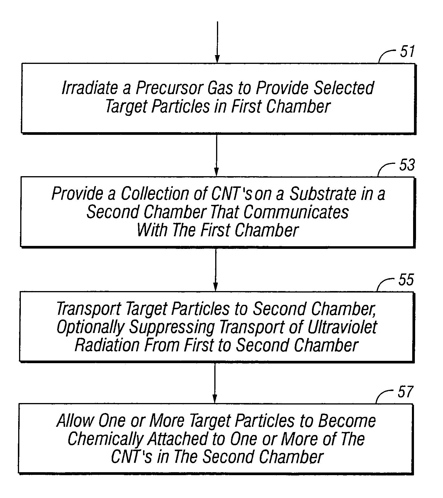
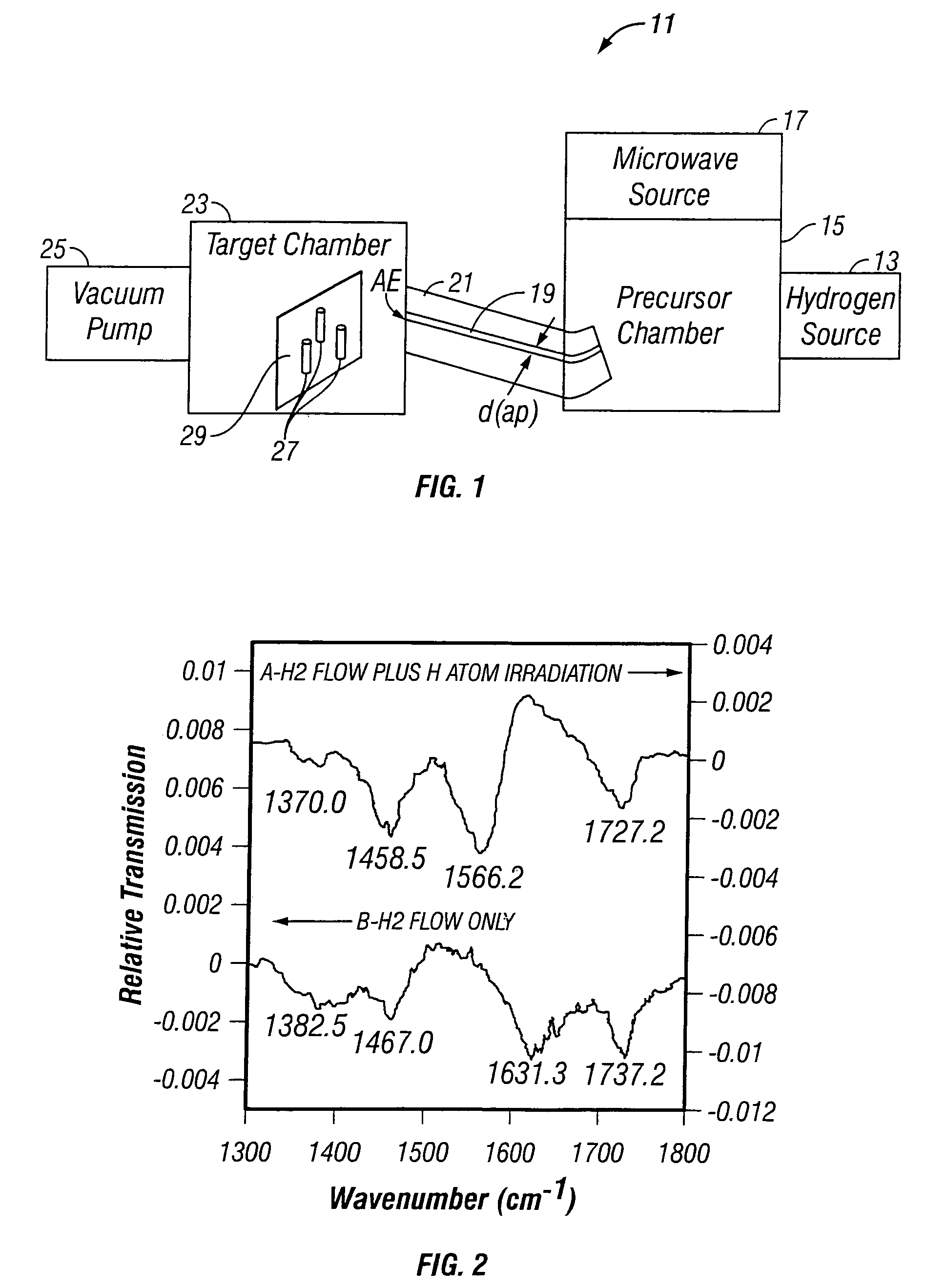
[0013]FIG. 1 illustrates a system 11 for practicing the invention to provide hydrogen as the species for functionalization of the CNTs. The system 11 includes a precursor source 13 that feeds hydrogen (e.g., molecular hydrogen, with a purity of 99.9999 percent or better) to a partially evacuated precursor chamber 15. Molecular hydrogen in the precursor chamber 15 is irradiated by a microwave source or other suitable radiation source 17, for example, a McCarroll cavity operating at 2.45 GHz and powered by an Opthos microwave generator. The radiation source 17 provides sufficient radiant energy to produce a cold plasma, in which the free electrons, with typical temperatures Te≈a few electron volts (1 eV corresponds to T=11,604 K), are much hotter than the resulting partially ionized gas, which has typical temperatures Tg≈350-1000 K. This discharge produces electrons by ionization and radicals, especially atomic hydrogen as a precursor particle, by dissociation.

[0014]Part of the atomic...


PUM

PropertyMeasurementUnit
Timeaaaaaaaaaa
Temperatureaaaaaaaaaa
Pressureaaaaaaaaaa

Abstract

Method and system for functionalizing a collection of carbon nanotubes (CNTs). A selected precursor gas (e.g., H2 or F2 or CnHm) is irradiated to provide a cold plasma of selected target particles, such as atomic H or F, in a first chamber. The target particles are directed toward an array of CNTs located in a second chamber while suppressing transport of ultraviolet radiation to the second chamber. A CNT array is functionalized with the target particles, at or below room temperature, to a point of saturation, in an exposure time interval no longer than about 30 sec.

Description

FIELD OF THE INVENTION[0001]This invention is related to addition of functional groups to collections of carbon nanotubes.BACKGROUND OF THE INVENTION[0002]Carbon nanotubes (CNTs) have attracted much attention, due to their extraordinary mechanical properties and their unique electronic properties. A CNT is topologically equivalent to a two-dimensional graphite sheet rolled into a cylinder, with a cylinder diameter as small as 0.7 nanometers (nm) and with a cylinder length up to several microns (μm). A CNT can be single walled (SW) or multiple walled (MW) and can also be fabricated as a nanofiber or other CNT structure. A CNT can be characterized by its chiral vector components (n,m), which helps determine tube diameter, electronic properties and other properties. Depending upon the chirality (n-m divisible by 3 or otherwise), a CNT can be conducting (metal-like) or semi conducting.[0003]CNTs are being studied for applications in high strength / low weight composites, membranes, mechan...

Claims


Application Information

Patent Timeline
02 Oct 2007
Publication
US7276266B1
IPC
H05H1/24
CPC
B82Y30/00; B82Y40/00; H05H3/02; C01B31/0273; Y10S427/102; C01B2202/02; C01B32/174
Inventors
KHARE, BISHUN N.; MEYYAPPAN, MEYYA