Sequential timebase

a timebase and sequential technology, applied in the direction of noise figure or signal-to-noise ratio measurement, instruments, structural/machine measurement, etc., can solve the problems of reducing the deterministic jitter, the scheme is prone to many problems, and the jitter specification of such a system degrades rapidly, so as to reduce deterministic jitter and generate a long delay

Active Publication Date: 2007-10-09
TELEDYNE LECROY
View PDF8 Cites 6 Cited by
  • Summary
  • Abstract
  • Description
  • Claims
  • Application Information

AI Technical Summary

Benefits of technology

[0015]In an oscilloscope, such as a LeCroy® sampling digital oscilloscope employing the present invention and operating at such a data acquisition speed, a periodic strobe output from a pulse generator may be generated, and correlated to a repetitive input signal, having less than 1 picosecond time resolution and less than a few picoseconds jitter for a delay range from about 20 nanoseconds to more than 1 microsecond. The invention employs a three part scheme for generating such a result. These include generating a fine analog delay by using a dual stage ramp providing a high time resolution, counting using a high-Q stabilized internal clock for generating a long delay and less jitter, and greatly reducing deterministic jitter caused by the combination of a finite settling time of a ramp hold signal. Aberrations of the ramp hold signal include hold decay and ramp non-linearity, and are addressed by using time difference information between the trigger and the internal clock, obtained by a TDC (time-to-digital converter) and a predetermined coarse delay count, to generate a calibration table to correct for various timing delays.
[0016]It is therefore an object of the invention to provide an improved method and apparatus for generating a stable, low jitter sequential timebase.

Problems solved by technology

However the latter is burdened with a choice between overall stability and a quick response.
As a result, the jitter specification employing such a system degrades rapidly as the delay time increases.
Prior attempts at providing such a predictable delay for a sequential timebase have met with less than complete success and generally fall into three categories.
This scheme runs into many problems as the length of time to be generated increases.
However, this flattening of the slope of the ramp introduces more substantial jitter when the ramp reaches the predetermined voltage level.
However, there are a number of problems with this type of system.
Indeed, U.S. Pat. No. 5,959,479 issued to Woodward, titled “Sampling Timebase System” (1999) describes that in such a sequential timebase system, the frequency stability of the startable oscillator is compromised since the startable oscillator is designed to have a quick startup time.
As a result, jitter becomes larger as the time delay increases.
However, while U.S. Pat. No. 4,260,912 professes a virtually jitter free timing interval, there is in fact substantial jitter produced in this arrangement because of non-linearities associated with each portion of the ramp, and there are settling time issues when the ramp is stopped and the ramp voltage is intended to be held constant.
However, the almost instantaneous synchronization of the sinusoidal signal phase to the external triggering event is not perfect due to nonlinear effects in the analog processing circuits in the phase startable clock device.
The non-ideal circuit operation translates into systematic trigger and gated clock or strobe timing delay errors.
These delay errors manifest themselves as deterministic jitter at the output of the timing circuit.
While this approach recognizes the jitter problem inherent in the timing circuit, the proposed response is inadequate to sufficiently reduce deterministic jitter.

Method used


Image

  • Sequential timebase
  • Sequential timebase
  • Sequential timebase

Examples


Embodiment Construction

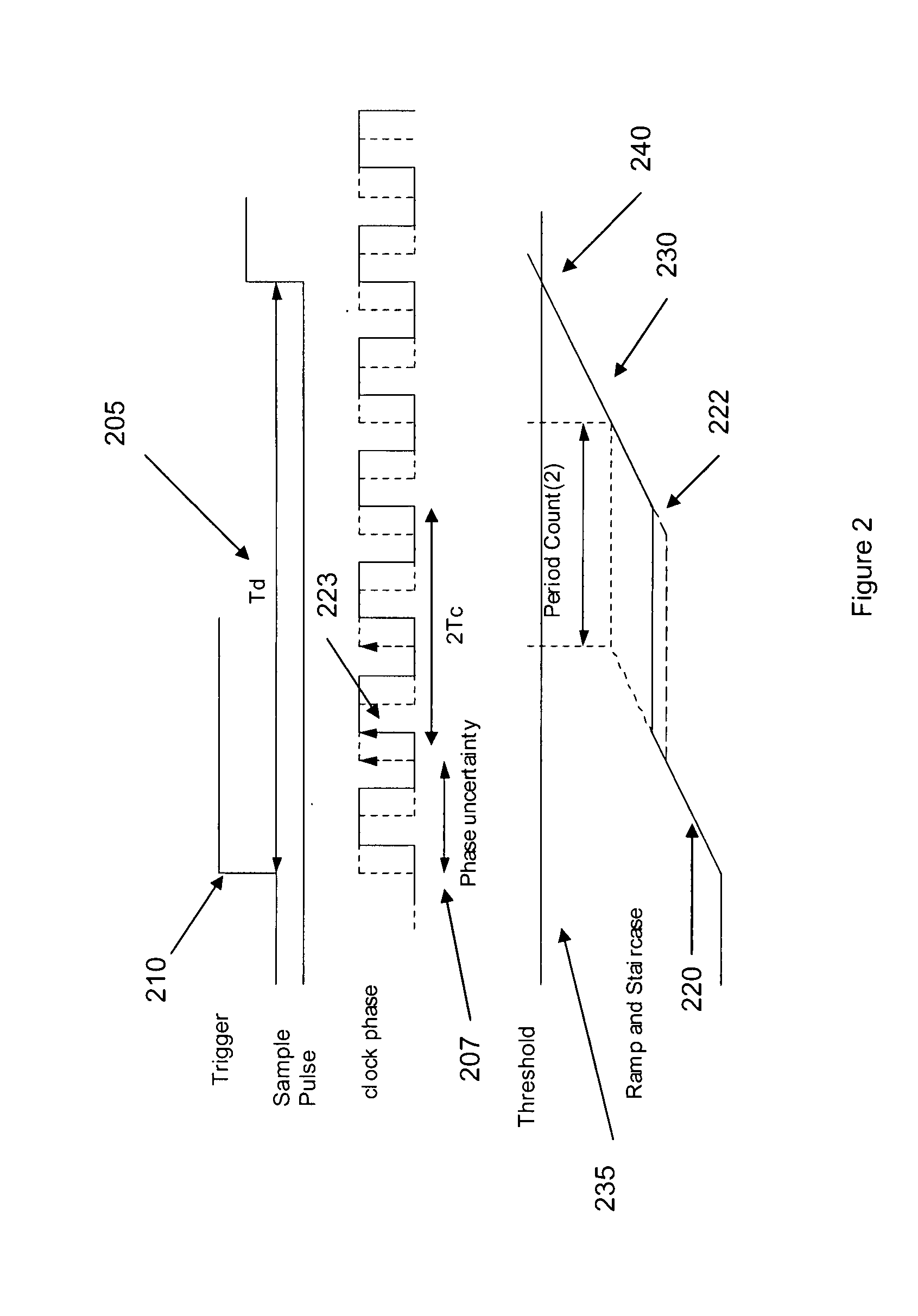
[0030]One possible architecture for a Delaying Pulse Generator (DPG) employing a dual stage ramp is presented in accordance with the invention in an attempt to provide a more precise elapsed time interval Td 205. As is shown in FIG. 2, when a trigger 210 is input to the DPG of the invention, the first portion 220 of the ramp is started. The ramp is stopped and the voltage 222 thereof is held steady upon reaching a predetermined number of clock pulses 223. In a preferred embodiment, the ramp voltage increase is stopped after two clock pulses are received. Of course, this could be any desired number of clock pulses selected to accommodate the ramp voltage slope, however, two or three clock pulses are preferred to reduce jitter. The important consideration is that the ramp stops synchronous with a clock pulse. The final value 222 of the first ramp 220 corresponds to a time difference between the trigger and designated clock pulse, which may be determined in accordance with a well known...


PUM


Abstract

A method and apparatus for correcting for deterministic jitter in a sequential sampling timebase. The value of a fine analog delay is held at a substantially constant nominal rate during a duration of a counting of a digital clock. A time difference between a trigger at which a fine analog delay starts measuring time and the occurrence of a digital pulse of a stable clock used to count a coarse delay is measured. An input waveform is sampled at a sample time having a nominal delay time. After sampling, a desired compensation time is provided for the sample of the input waveform in accordance with combinations of three independent variables defining a calibration table. The waveform is reconstructed by shifting a delay time of a sampled value of the input waveform from its nominal delay time in accordance with a value defined by the calibration table.

Description

CROSS REFERENCE TO RELATED APPLICATIONS[0001]This application claims the benefit of U.S. Provisional Patent Application Ser. No. 60 / 650,985, entitled “Sampling Scope”, filed Feb. 7, 2005, and U.S. Provisional Patent Application Ser. No. 60 / 656,617, entitled “Sequential Timebase”, filed Feb. 25, 2005.FIELD OF THE INVENTION[0002]The present invention is particularly concerned with a digital storage oscilloscope (DSO) employing a sequential sampling scheme, an equivalent time sampling method that allows a user to measure repetitive input signals with fine time resolution and a targeted delay range. A digital oscilloscope based on this invention can acquire waveforms with high time resolution while greatly reducing deterministic jitter.BACKGROUND OF THE INVENTION[0003]A sequential time base acts as a kind of pulse generator, the input to which is an external repetitive (but sometimes aperiodic) trigger signal, and the output of which is a sampling pulse that is delayed from the trigger ...

Claims


Application Information

Patent Timeline
Patent Type & Authority Patents(United States)
IPC IPC(8): G01D18/00G01M99/00
CPCG01R35/002G01R13/0254
Inventor KOBAYASHI, KENSUKE
Owner TELEDYNE LECROY
Why Eureka
Try Eureka