Supercharging system for internal combustion engine

a technology for internal combustion engines and supercharging systems, which is applied in the direction of combustion-air/fuel-air treatment, machines/engines, fuel air intakes, etc. it can solve the problems of high cost, deformation, damage, etc., and achieves simple structure, improved economical efficiency in device use, and small size

Inactive Publication Date: 2007-10-16
USUI KOKUSAI SANGYO KAISHA LTD
View PDF35 Cites 69 Cited by
  • Summary
  • Abstract
  • Description
  • Claims
  • Application Information

AI Technical Summary

Benefits of technology

[0019]This invention is thus structured, in which the exhaust gas flowing through the exhaust introduction passage flows into the mixture part having the flow passage of a smaller diameter than the exhaust introduction passage, so that flow velocity of the exhaust gas is accelerated, and thus an inside of the mixture part is rendered under negative pressure. With use of this negative pressure, outside air is absorbed through the absorption passage into an inside of the mixture part, thereby being mixed with the exhaust gas inside the mixture part, so that the mixed gas is exhausted through the exhaust discharge passage to an exterior while a part of the mixed gas, at the same time, is introduced into an inside of the intake passage and returned through the intake passage to the internal combustion engine. Thus, it becomes possible to absorb the outside air and to mix the outside air and the exhaust gas upon recovery of kinetic energy of the exhaust gas, so that energy can be effectively reused to improve the economical efficiency in use of the device. Furthermore, since the turbocharger or the like does not need to be formed, the supercharging system for the internal combustion engine can be obtained with the simple structure and the plain manufacturing art. The mixing action of the outside air and the exhaust gas causes cooling effect on the exhaust gas, so that the intercooler, the EGR gas cooler, or the like does not need to be formed, or even where formed, these coolers in smaller size than conventional coolers can be sufficient.
[0020]With this EGR system, a device such as having both supercharging system and the EGR gas cooler can be obtained, so that the number of components can be reduced, and the EGR system can be, e.g., simplified and reduced in size as well as weight. As the result, the products at low price can be obtain upon reduction in manufacturing costs, while the products having the superior layout property installable to the limited space such as, e.g., the engine room or the like can be obtained. Furthermore, the simple structure makes it possible to obtain products having the superior durability, in which any damage nor deformation hardly occurs while maintenance work or the like is easy.

Problems solved by technology

With a supercharger such as, e.g., a turbocharger or the like, however, a structure is complicated to result in high costs while ingression of extraneous substances such as, e.g., stones, sands, etc. into a compressor or a turbine, introduction of exhaust gas at excessively high temperature, or the like occasionally causes a component such as, e.g., a bearing, a seal, a shaft, etc. to get damaged, deformed, or stuck, or causes oil to leak, so that maintenance and so on have been troublesome for taking effort and time.
Furthermore, the supercharger or an intercooler needs to be formed separately from an EGR gas system, and further the EGR gas system has an EGR gas cooler, so that the EGR system becomes complicated and larger in size.

Method used


Image

  • Supercharging system for internal combustion engine
  • Supercharging system for internal combustion engine
  • Supercharging system for internal combustion engine

Examples


first embodiment

The First Embodiment

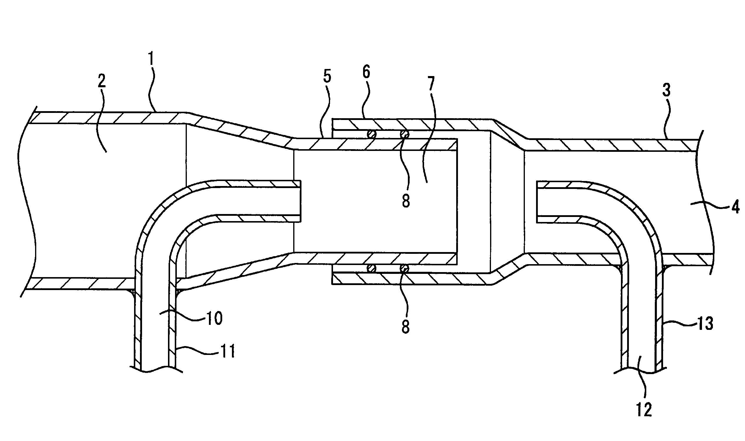
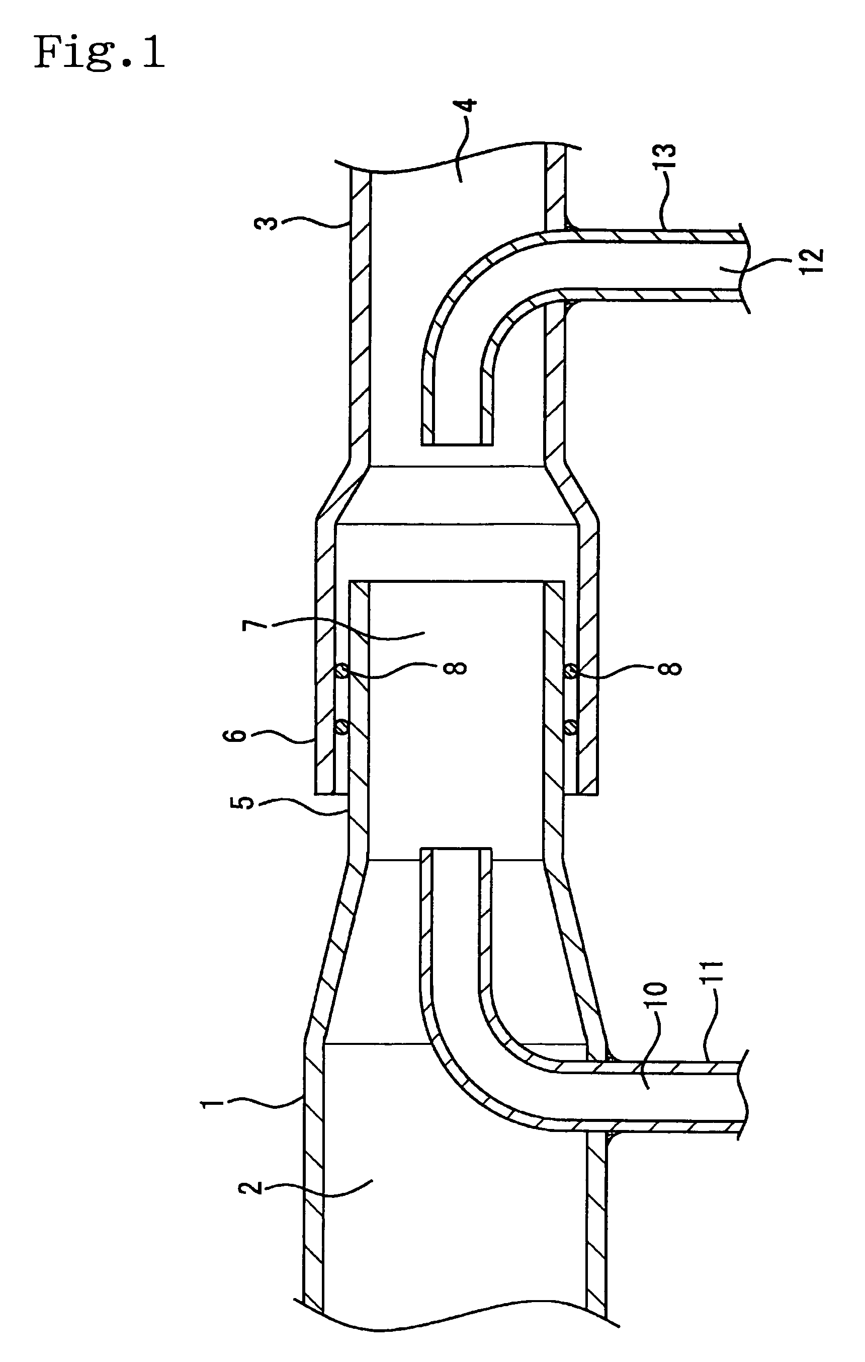
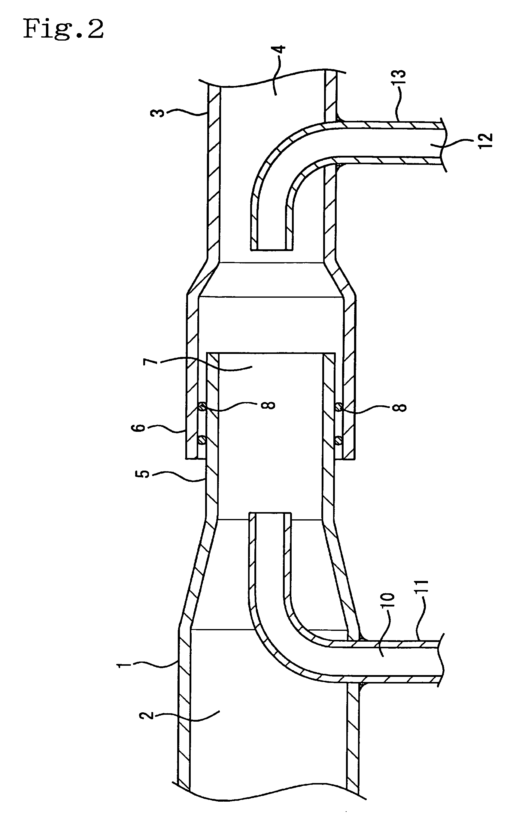
[0030]Hereinafter, the first embodiment in which this invention is applied to an EGR system for automobiles is described in reference to FIG. 1 and FIG. 2. Numeral 1 is an exhaust introduction pipe arranged inside with an exhaust introduction passage 2 through which exhaust gas flows after flowing out of an exhaust manifold. A front end of the exhaust introduction pipe 1 is connected in series with a discharge outlet pipe 3 arranged with an exhaust discharge passage 4, in which the exhaust gas flowing through the exhaust introduction pipe is introduced into the exhaust discharge passage 4 and thereafter exhausted through a muffler or the like to an exterior. The first discharge pipe 3 and the exhaust introduction pipe 1 are connected since a front end side of the exhaust introduction pipe 1 is formed to have a smaller diameter than a body part thereof and arranged with a small diameter part 5 of a prescribed length, having a smaller diameter than the exhaust intr...

second embodiment

The Second Embodiment

[0040]In the above described first embodiment, the absorption pipe 11 is disposed separately from the exhaust introduction pipe 1 and the first discharge pipe 3 to arrange the absorption passage 10, however, in another different embodiment, i.e., in the second embodiment, as shown in FIG. 3, the small diameter part 5 of the exhaust introduction pipe 1 is inserted as disposed into the first discharge pipe 3 in letter L shape, having the larger inner diameter than the small diameter part 5. The gap part formed between the small diameter part 5 and the first inlet pipe 3 is set as the absorption passage 10 for absorbing the outside air, and the first inlet pipe 3 is connected to the side of the intake manifold. A holder part 14 in a circular cylinder shape is fastened to around the a bent part of the first discharge pipe 3, in which the exhaust discharge passage 4 for the exhaust gas is arranged inside the holder part 14 while the second discharge pipe 13 to be con...

third embodiment

The Third Embodiment

[0046]According to the above described first embodiment, the exhaust gas can be cooled down since that the absorption pipe 11 is disposed as penetrating and inserted inside the exhaust introduction pipe 1, and the outside air absorbed into the absorption passage 10 arranged to the absorption pipe 11 is supplied to the inside of the mixture part 7 to be mixed with the exhaust gas inside the mixture part 7, however, according to the third embodiment of this invention, as shown in FIG. 4, the absorbed outside air can be previously cooled down upon arranging an air cooler 15 to the absorption passage 10, and the cooling effect on the exhaust gas inside the mixture part 7 can be further enhanced upon supplying the cooled outside air into the inside of the mixture part 7.

[0047]The third embodiment is described in reference to FIG. 4, in which the air cooler 15 is arranged to a proximal end side of the absorption pipe 11 projecting from the exhaust introduction pipe 1 t...


PUM


Abstract

A supercharging system for an internal combustion engine includes an exhaust introduction passage for introducing exhaust gas from an internal combustion engine; an exhaust discharge passage for introducing the exhaust gas from the exhaust introduction passage and exhausting the exhaust gas to an exterior; a mixture part arranged between the exhaust introduction passage and the exhaust discharge passage, for changing internal pressure into negative pressure upon accelerating flowing velocity of the exhaust gas with a narrowed flowing passage set to have a smaller diameter than the exhaust introduction pipe; an absorption passage for mixing outside air and the exhaust gas inside the mixture part upon introducing the outside air with use of negative pressure into an inside of the mixture part; and an intake passage for taking out and returning a part of mixed gas mixed inside the mixture part to a side of the internal combustion engine.

Description

BACKGROUND OF THE INVENTION[0001]1. Field of the Invention[0002]This invention relates to a supercharging system for an internal combustion engine in which a part of exhaust is mixed with intake air and returned to the internal combustion engine.[0003]2. Description of Related Art[0004]Conventionally, EGR systems in which a part of exhaust gas is taken out of an exhaust gas system and returned to an intake system of the engine to be added to mixture gas and intake air, such as disclosed in, e.g., Japanese Unexamined Patent Publication Nos. S60-237,153, H11-62,632, H11-182,358, and 2003-286,871, have been used in engines for automobiles along with gasoline engines and diesel engines. The EGR system has a supercharger such as, e.g., a turbocharger or the like, in which a turbine of the turbocharger is driven by the exhaust gas exhausted from the internal combustion engine to render the compressor rotate to take in and compress outside air, and the compressed air is then supplied into ...

Claims


Application Information

Patent Timeline
Patent Type & Authority Patents(United States)
IPC IPC(8): F02M25/07F01N3/02F01N3/10F01N5/00F01N7/20F01N13/08F02B27/00F02B37/00F02M35/10
CPCF02M25/0704F02M25/0717F02M25/0742F02M35/10222F02B29/0406Y02T10/121F02M25/0727F02M26/14F02M26/02F02M26/23F02M26/36
Inventor USUI, MASAYOSHI
Owner USUI KOKUSAI SANGYO KAISHA LTD
Why Eureka
Try Eureka