

Ultra broadband linear antenna
a linear antenna and ultra-broadband technology, applied in the field of communication, can solve the problems of difficult to obtain relative constant characteristics, limited operational bandwidth of antennas, and significant limitations of ideal antennas, and achieve the effect of increasing frequency range and constant performan
- Summary
- Abstract
- Description
- Claims
- Application Information
AI Technical Summary
Benefits of technology
Problems solved by technology
Method used
Image

Examples
Embodiment Construction
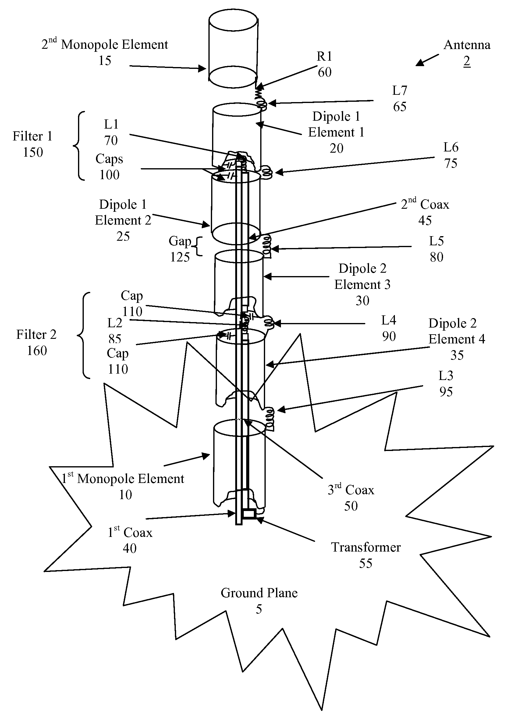
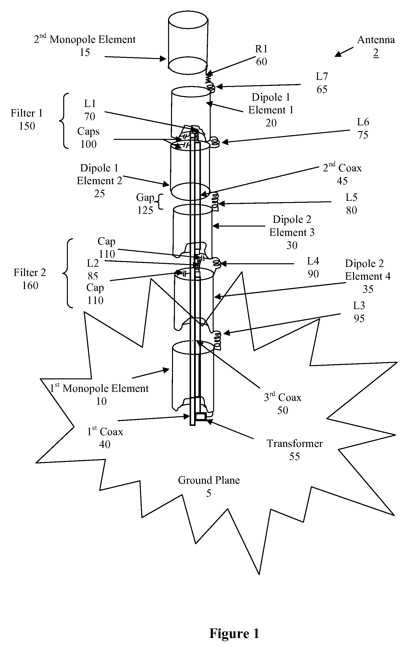
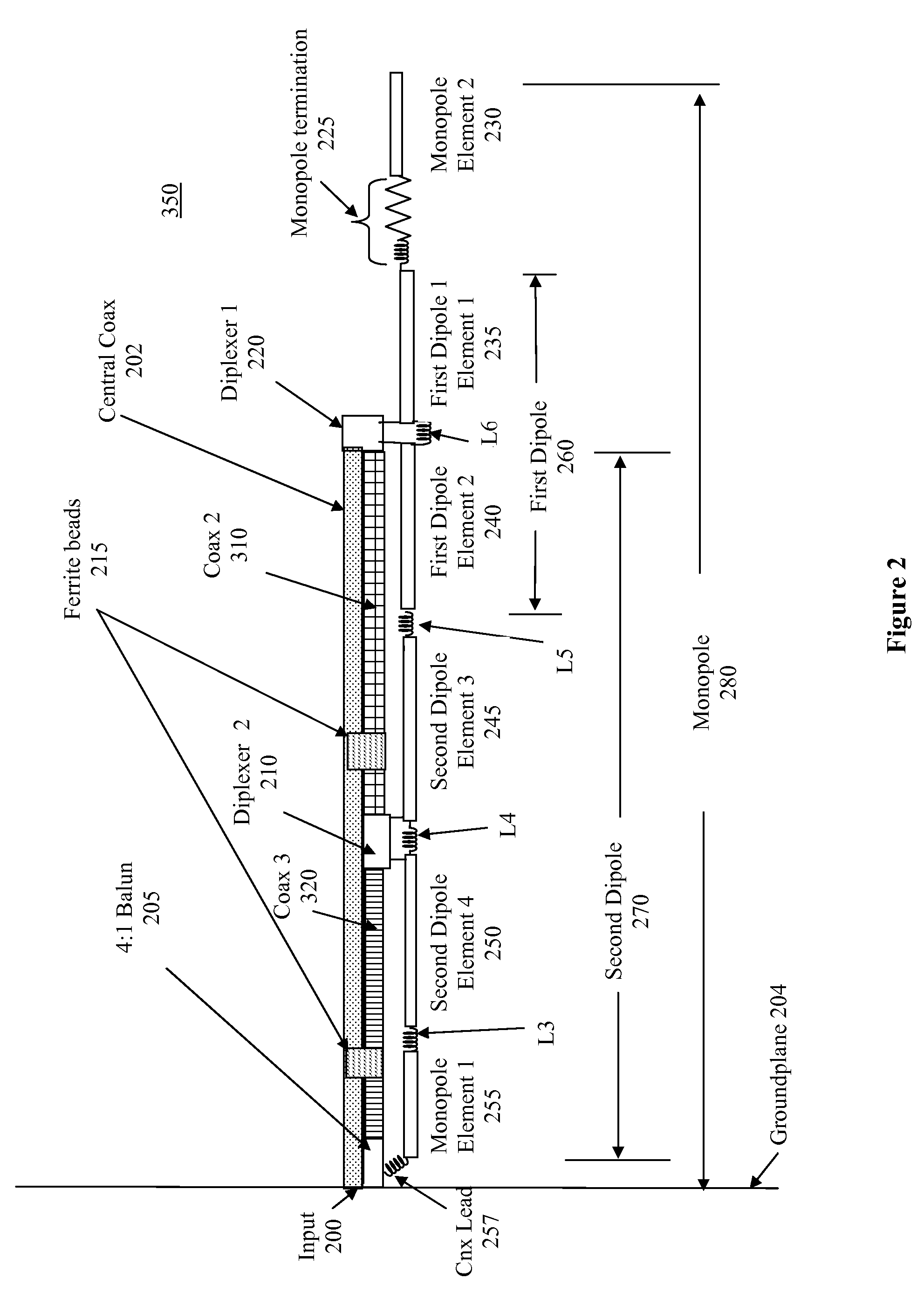
[0029]The present invention relates to an antenna that combines dipole and monopole antenna elements with filtering in order to achieve a greater bandwidth. For example, the present invention teaches a system to achieve bandwidths of 50:1 or greater, for example a range of about 30 MHz to 1500 MHz. The term wideband ultra wideband and similar terms have equivalent meanings ad described herein unless otherwise indicated.
[0030]The present filter designs have several short comings as described herein. One such short coming is that only two terminals are typically provided for any filtering action. The present invention provides multiple applications of multi-terminal filters which allow a much more extensive use of filter concepts. In one embodiment, a number of dipole antenna sections surround a central feed coax and have monopole antenna elements at the ends, wherein the coax extends the full antenna length from a ground or reference plane. A further embodiment uses a filter designat...
PUM
 Abstract
Description
Claims
Application Information