Molding system having a micro heating element for molding a micro pattern structure

a technology of heating element and mold, which is applied in the direction of photomechanical equipment, manufacturing tools, instruments, etc., can solve the problems of increasing residual stress, difficult to completely transfer the micro/nano pattern, and difficult to heat and cool the mold, so as to prevent a solidifying layer, quick heat and cooling, and enhance the transcribability of the micro pattern

Inactive Publication Date: 2007-11-06
IND ACADEMIC CORP FOUND YONSEI UNIV
View PDF5 Cites 8 Cited by
  • Summary
  • Abstract
  • Description
  • Claims
  • Application Information

AI Technical Summary

Benefits of technology

[0027]To solve the above problems, the present invention is provided with a micro heating elements between a mold and a mold insert with a micro / nano pattern so that the micro heating element can quickly heat and cool the mold insert in the middle of a molding process. Through this, it is possible to prevent a solidified layer from being created in the molding process, especially an injection molding or injection compression molding and in result, enhance transcribability for a micro pattern. In addition, it is possible to decrease flow resistance against a resin and prevent a residual stress from being produced in products and in result, form the high-performance micro / nano pattern plastic products with excellent precision and optical properties.
[0028]The present invention can quickly heat and cool a wall of a cavity in the middle of the molding process. Therefore, even if a length (l) of the cavity is much larger than a thickness (t) thereof and the mold insert has a micro pattern, it is possible to form products with excellent transcribability.
[0029]In the compression molding and hot embossing molding, a more effective molding is also possible by quickly heating and cooling predetermined parts of the mold insert.
[0030]Another object of the present invention is to fabricating a heater and a sensor through a batch processing or a relatively simple processing, by which it is possible to lower a fabrication time and effort.
[0031]Still another object of the present invention is to more improve mechanical and optical properties of products by detecting local properties (temperature, pressure) and executing a local heating based on them. To achieve this object, the plurality of the heaters and the plurality of the sensors are formed on the mold insert in an integrated manner.
[0032]According to a preferred embodiment of the present invention, the pressure as well as the temperature of the mold insert is measured. From the pressure and temperature, we can obtain a filling speed of the resin, a flow rate. These data are used in an analysis of the stress inside of the resin. The pressure data and the temperature data are organized to form a database. This database will be used in the following molding process. We will be able to know the state of the molding material in a very short time using this database.

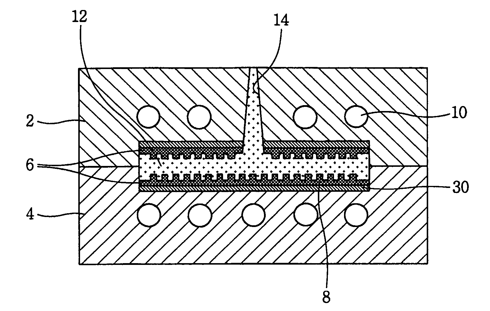
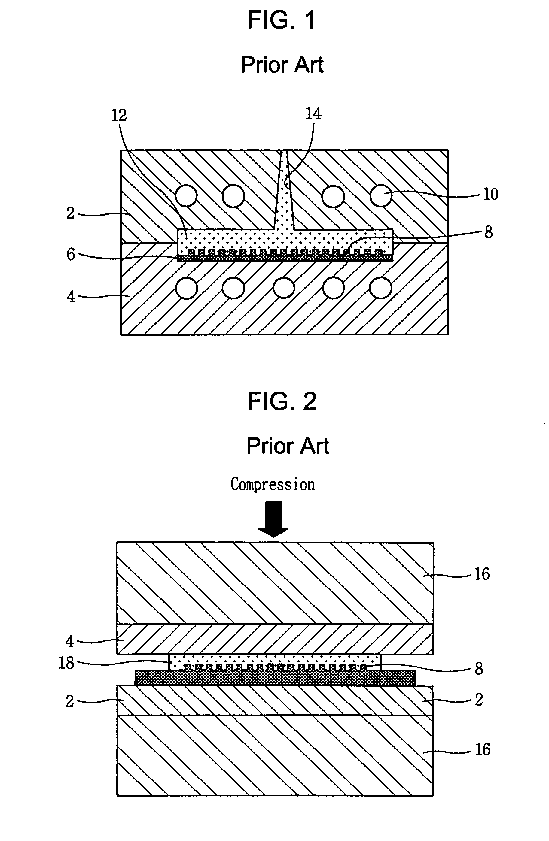
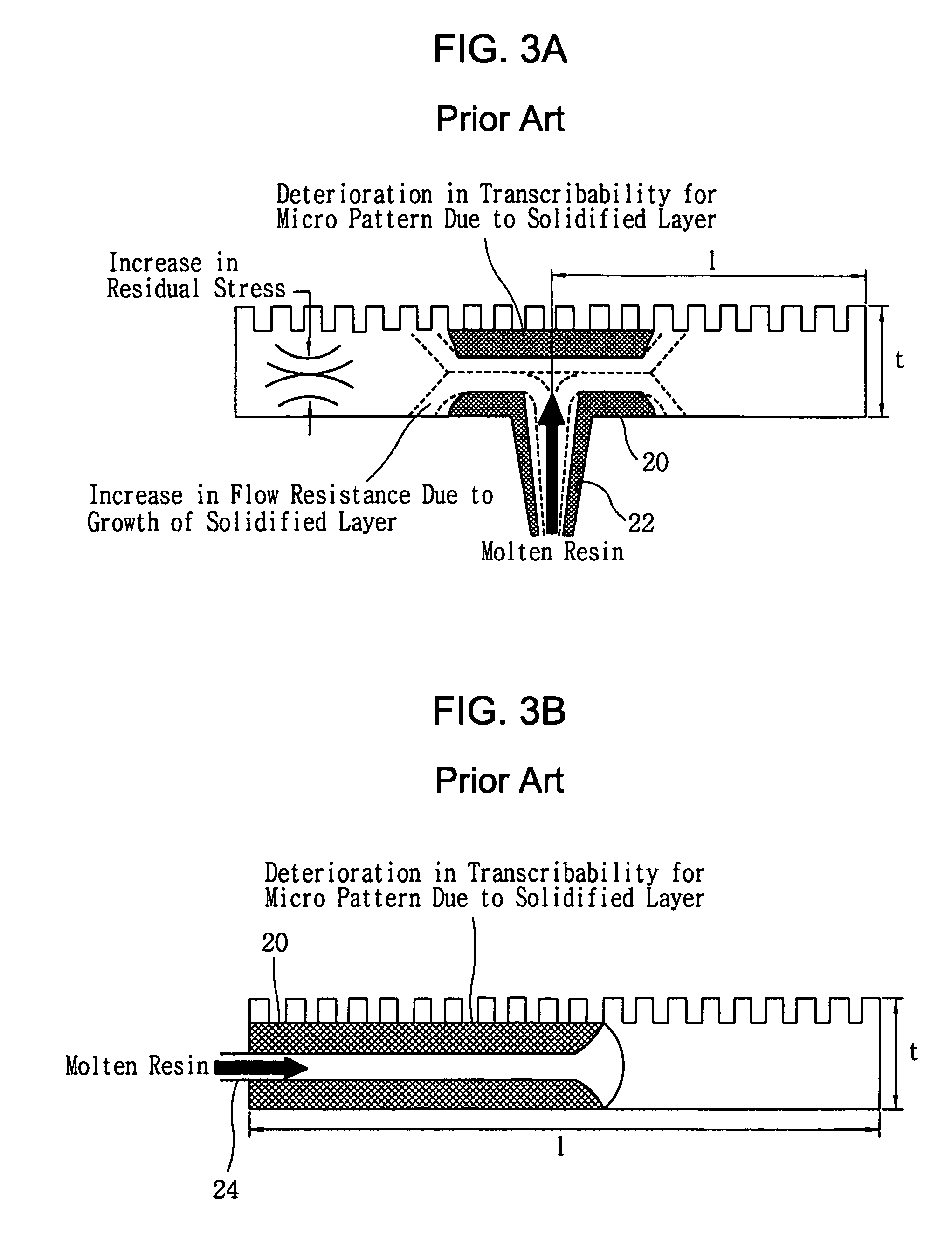
Problems solved by technology

However, in the above molding systems, a quick heating and cooling is difficult and thus there are many problems.
Once the solidified layer is created, fluidity deteriorates and in result, it is difficult to completely transfer the micro / nano pattern.
In addition, low fluidity makes the pressure applied onto the resein and the residual stress increase, which deteriorates mechanical and optical performance of products.
If a length of the cavity is large in comparison with a thickness thereof, these problems become worse and a more serious defect is caused.
However, if the size is smaller, that is, if the thickness is smaller than 0.6 mm, a complete filling during the injection molding is difficult due to the solidified layer.
Even if a complete filling is attained, properties of the substrate become worse due to the residual stress.
These problems are not only for the optical disc substrate but also for other high-performance plastic goods with a micro pattern.
In the compression molding and hot embossing molding, a conventional molding system has a disadvantage that because the whole of the mold has to be heated / cooled, a heating / cooling time is long and effectiveness of heating / cooling is low.
However, these molding systems have disadvantages below.
This deteriorates transcribability for a micro pattern on the mold insert.
Therefore, these molding systems are not suitable to form a micro pattern structure.
This conventional way requires much processing time and effort.
Furthermore, it is very difficult to form a micro heater and a micro sensor at an exact position by the conventional way.
Especially, if the plurality of the micro heaters and the plurality of the micro temperature sensors have to be formed, it is almost impossible to form them at exact positions by the conventional way.
More importantly, the temperature controllability is still bad in these molding systems.
We know from a theory, experience or experiment that the temperature is not uniform throughout a molding material in the middle of the molding process.
This non-uniformity of local temperatures means that the solidification of the molding material proceeds at different speeds.
In result, a deformation of the products is caused and optical properties of the products deteriorate.
These problems have a very serious effect on the molding process for a structure with a micro pattern on it, such as an optical disc substrate, a light guide plate, a micro lens array and a diffraction optical device, because a defect, even if very slight, has a very serious effect on the micro pattern structure in proportion to its precision.

Method used


Image

  • Molding system having a micro heating element for molding a micro pattern structure
  • Molding system having a micro heating element for molding a micro pattern structure
  • Molding system having a micro heating element for molding a micro pattern structure

Examples


Embodiment Construction

[0044]A molding system for molding a micro pattern structure having a micro heating element and a method for fabricating a mold insert for molding a micro pattern structure used therein in accordance with the present invention will now be described in detail with reference to the accompanying drawings.

[0045]The present invention is characterized in that it is possible to quickly heat and cool the mold insert 6 with a micro / nano pattern using a micro heater 32 formed in an integrated manner by using a MEMS (MicroElectroMechanical Systems) process, by which it is possible to improve transcribability for the micro / nano pattern and produce a high-performance micro-pattern structure with excellent properties.

[0046]In a molding system according to a preferred embodiment of the present invention, the micro heating element 30 with a MEMS structure which can control a temperature of the mold insert 6 by heating it is formed between the mold insert 6 and a mold. FIG. 5 is a side view of a mol...


PUM

PropertyMeasurementUnit
thicknessaaaaaaaaaa
diameteraaaaaaaaaa
temperatureaaaaaaaaaa

Abstract

A molding system for molding a micro pattern structure includes a mold; a mold insert 6 having a micro pattern, the mold insert 6 being fixed to the mold; and a micro heating element 30 having a micro heater 32 between the mold and the mold insert 6, the micro heater 32 being formed in an integrated manner by using a MEMS process; wherein the amount of Joule's heat produced by the micro heater 32 is controlled by controlling the amount of electricity applied to the micro heater 32 so as to control a temperature of the mold insert 6. A method for fabricating the mold insert 6 for molding the micro pattern structure, the mold insert 6 being heated by a micro heater 32, includes the steps of: coating a photoresist on a back side of either the mold insert 6 or a plate 40 fixed onto the mold insert 6; patterning the photoresist by removing a part of the photoresist corresponding to the micro heater 32 using a lithography process; coating a material for forming the micro heater 32; and removing the residual photoresist.

Description

BACKGROUND OF THE INVENTION[0001]This application claims the priority of Korean Patent Application No. 10-2002-0088039, filed on Dec. 31, 2002 in the Korean Intellectual Property Office, and PCT / KR2003 / 002939, filed Dec. 31, 2003, the disclosures of which are incorporated herein in their entirety by reference.[0002]1. Field of the Invention[0003]The present invention relates to a molding system having a micro heating element and a method for fabricating a mold insert used therein. More particularly, the present invention relates to the molding system for molding a micro pattern structure having the micro heating element which includes a micro heater formed in an integrated manner by using a MEMS (MicroElectroMechanical Systems) process, and the method for fabricating the mold insert for molding the micro pattern structure used therein.[0004]2. Description of the Related Art[0005]Now, an injection molding, an injection compression molding, a compression molding and a hot embossing mo...

Claims


Application Information

Patent Timeline
Patent Type & Authority Patents(United States)
IPC IPC(8): B29C45/73B29C33/38B29C45/26B29C45/77B29C45/78G11B7/26
CPCG11B7/263B29C45/2642B29C45/78B29D17/005B82Y10/00B82Y40/00G03F7/0002B29C45/2632B29C33/3842B29C45/77B29C2945/76006B29C2945/7604B29C2945/76294B29C2945/76454B29C2945/76458B29C2945/76525B29C2945/76531B29C2945/76732B29C2945/76772B29C2945/76946B29L2017/005B29C45/73
Inventor KANG, SHINILL
Owner IND ACADEMIC CORP FOUND YONSEI UNIV
Why Eureka
Try Eureka