Direct conversion receiver

Inactive Publication Date: 2007-11-06
ALCATEL LUCENT SAS
View PDF9 Cites 8 Cited by
  • Summary
  • Abstract
  • Description
  • Claims
  • Application Information

AI Technical Summary

Benefits of technology

[0009]As a summary the patent applies to any receiver where an analog complex representation of the received band is digitized by a set of A to D converters.
[0010]According to a first embodiment the compensating coefficients are calculated from the translated down-converted carrier signals as output by the DDC-units and provided to compensator stages which are connected in series behind said DDC-units, respectively. Due to said open loop construction an iterative adaptation of the compensating coefficient is neither possible nor required because the accuracy of the calculated compensating coefficient is sufficient to achieve a proper removement of the image signals for most applications.
[0011]According to several other embodiments of the invention, the compensating coefficient is calculated in an iterative process in which the at least partially cleaned output signal of the direct conversion receiver are considered.
[0012]However, the process for optimizing the compensating coefficients according to the invention is rather quick

Problems solved by technology

Disadvantageously the down-converting process results in that the first carrier signal includes an image signal of said second carrier signal and vice versa.
These image signals are undesired because they make a reconstruction of the desired carrier signal more difficult.
The difficulty of reconstruction depends on the ratio of image signal to carrier signal which itself depends on the level of impairments in the realisation of the analog quadrature demodulator (gain, phase & quadrature m

Method used


Image

  • Direct conversion receiver
  • Direct conversion receiver
  • Direct conversion receiver

Examples


first embodiment

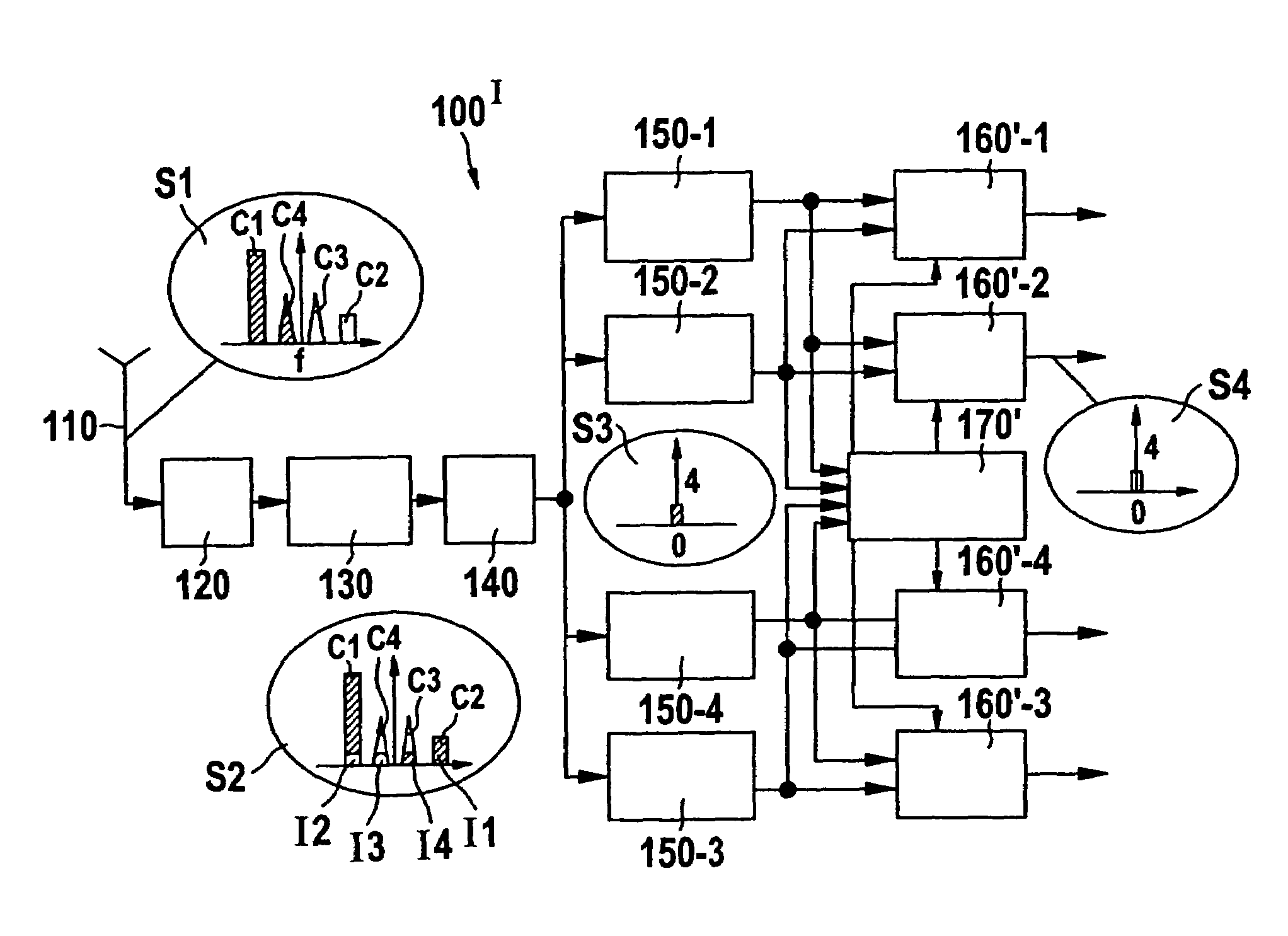
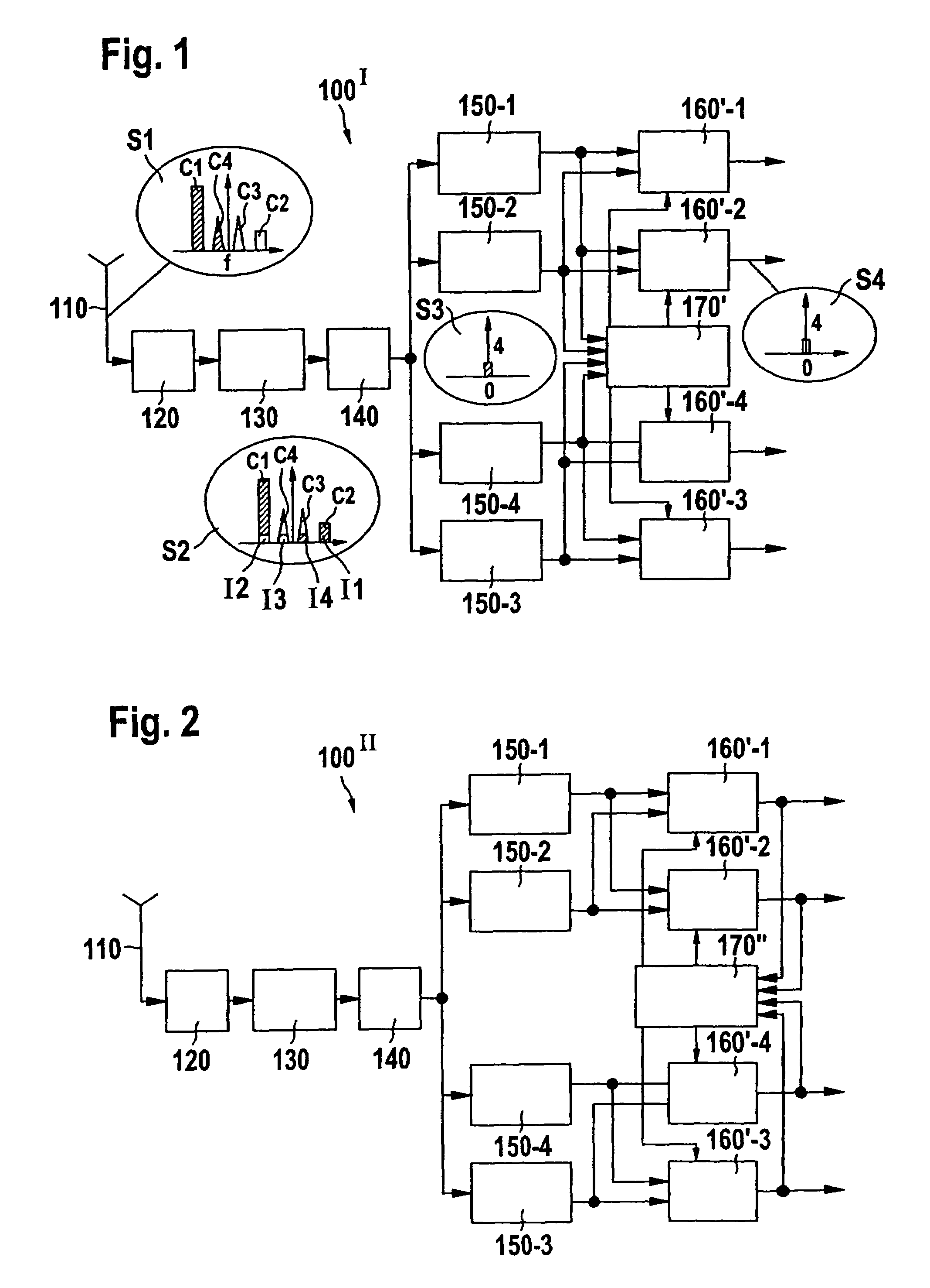
[0023]FIG. 1 shows the direct conversion receiver DCR 100′ according to the invention.

[0024]Said DCR 100′ serves for receiving a multi-carrier signal including at least a first and a second carrier signal—see spot S1—being located at image carrier frequencies via an antenna 110. After passing a front end 120 that can include itself some frequency band transposition the multi-carrier signal is directly down-converted to base band by a quadrature demodulator 130. The limited image rejection capabilities of said traditional quadrature demodulator 130 cause a superposition of the desired carrier signals and their images as described above by referring to FIG. 7. This effect is further illustrated for a multi-carrier signal comprising four carrier signals C1, C2, C3 and C4 by the spots S1 and S2 shown in FIG. 1. The images caused by the carrier signals C1 . . . C4 are assigned by the reference numerals I1 . . . I4, respectively.

[0025]After being output by the quadrature demodulator 130 t...

second embodiment

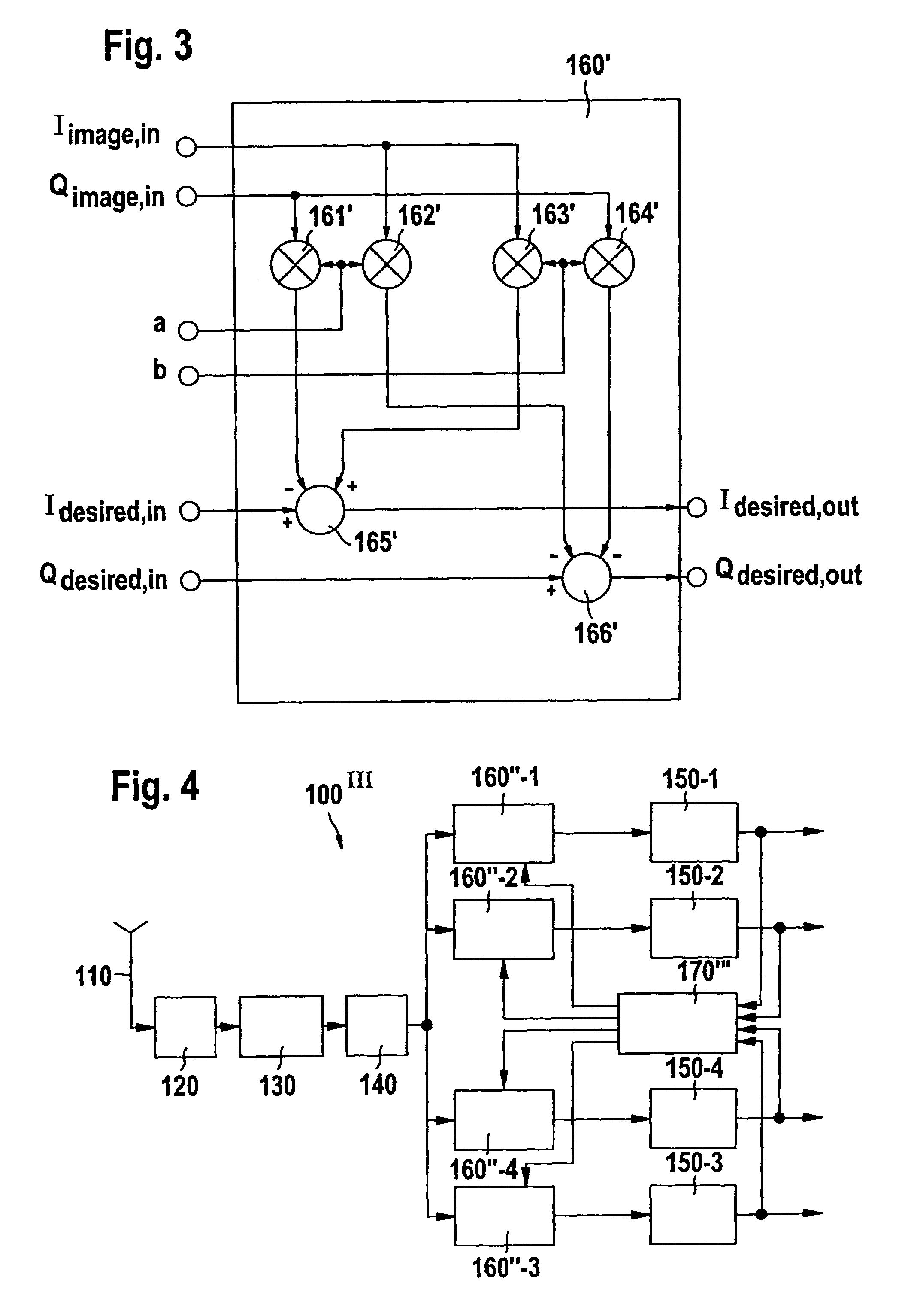
[0037]FIG. 3 shows a preferred embodiment of the indirect compensator stages 160′-1 . . . 160′-4 as used in the first and second embodiment of the DCR in FIGS. 1 and 2, respectively.

[0038]From FIG. 3 it is apparent that each of the compensator stages receives the real component Idesired, in of the translated carrier signal to be cleaned. Further, the imaginary component Qdesired, in of the translated carrier signal to be cleaned is received. For calculating the cleaned components Idesired, out and Qdesired, out the compensator stages 160′ further receive the real component Iimage, in of that translated carrier signal, an image of which is included in the translated carrier signal which is desired to be cleaned. Further, the indirect compensator stage 160′ receives the imaginary component Qimage, in of the translated carrier signal an image of which is included in the translated carrier signal desired to be cleaned at the port. Finally, the indirect compensator stage 160 receives the...

third embodiment

[0050]FIG. 4 shows the direct conversion receiver according to the invention. The operation of the antenna 110, the front end 120, the quadrature demodulator 130, the A / D-converter 140 and of the direct down-converters 150-1 . . . 150-4 and the operations of these components are the same as described above.

[0051]However, the third embodiment of the direct conversion receiver differs from the second embodiment substantially in that the compensator stages 160″-1 . . . 160″-4 are now connected in series between the A / D-converter 140 and the digital down-converters 150-1. Thus, the digitized multi-carrier signal output by said A / D-converter 140 is now received by said compensator stages 160″-1 . . . 160″-4 and these compensator stages output a cleaned multi-carrier signal; i.e. the output multi-carrier signal is substantially free of undesired image signals. The cleaned multi-carrier signals output by the compensator stages 160″-1 . . . 160″-4 are received by the individually co-ordinat...


PUM


Abstract

The invention relates to a direct conversion receiver for down-converting a received multi-carrier signal comprising at least a first and a second carrier signal at image carrier frequencies to a base band resulting in that the first carrier signal includes an image signal of said second carrier signal. Further, the known direct conversion receiver comprises at least a first and a second digital down-converter unit for separating the first and the second carrier signal from the down-converted multi-carrier signal after digitization. In order to make such receivers less complex and adjust them for fast time varying szenarios it is proposed to provide an error estimating unit to said receivers for calculating a compensating coefficient representing the quota and/or the phase position of the image signal of the second carrier signal being included in the first carrier signal and to remove the undesired image signal in response to said compensating coefficient.

Description

TECHNICAL FIELD[0001]The invention relates to a direct conversion receiver DCR, for receiving a multi-carrier signal including at least a first and a second carrier signal, being located at a first and second image carrier frequency, respectively, via an antenna. The invention further relates to a method for receiving such a multi-carrier signal, a computer program for carrying out such a method and an error estimating unit as well as to a compensator stage of such a direct conversion receiver. The invention is based on a priority reference EP 02 360 380.6 which is hereby incorporated by reference.BACKGROUND OF THE INVENTION[0002]Direct conversion receivers DCR are substantially known in the art. They typically comprise a front end unit for receiving the multi-carrier signal from the antenna and a quadrature demodulator for down-converting said received multi-carrier signal to a base band. Disadvantageously the down-converting process results in that the first carrier signal include...

Claims


Application Information

Patent Timeline
IPC IPC(8): H04B1/26H04B1/10H03D3/00H04B1/30H04L27/26H04L27/38
CPCH03D3/007H04L27/3854H04L27/2647H04B1/30
Inventor ENDRESS, FRIEDRICHDARTOIS, LUC
Owner ALCATEL LUCENT SAS
Why Eureka
Try Eureka