Surface modified stamper for imprint lithography

a technology of imprint lithography and stamping layer, which is applied in the field of surface modified stamping plate for imprint lithography, can solve the problems of non-uniform replication and sticking of thermoplastic polymer materials to the molding layer, uneven uniformity and sticking difficulties, and degradation of the dimensional integrity of the imprinted pattern or feature, so as to improve the release effect, minimize, if not completely eliminate, and improve the effect of releasing properties

Inactive Publication Date: 2007-11-13
SEAGATE TECH LLC
View PDF31 Cites 63 Cited by
  • Summary
  • Abstract
  • Description
  • Claims
  • Application Information

AI Technical Summary

Benefits of technology

[0011]An advantage of the present invention is a stamper suitable for imprint lithography of a substrate surface, where the surface of the stamper has been modified to enhance its releasing properties.
[0012]Another advantage of the present invention is a method of fabricating a coated stamper suitable for imprint lithography.
[0013]Additional advantages and other aspects and features of the present invention will be set forth in the description which follows and in part will become apparent to those having ordinary skill in the art upon examination of the following or may be learned from the practice of the present invention. The advantages of the present invention may be realized and obtained as particularly pointed out in the appended claims.
[0014]According to an aspect of the present invention, the foregoing and other advantages are obtained in part by a stamper suitable for thermal imprint lithography. The stamper comprises an imprinting surface having at least one sub-micron feature and a thin lubricant coating on the imprint surface having the feature. The inventive stamper of the present invention advantageously has a lubricant coating that has a thickness less than the smallest dimensioned feature on the imprinting surface, e.g. less than about 100 nm.
[0015]In accordance with embodiments of the present invention, the stamper comprises a main body and an imprinting surface having a negative image, e.g. a plurality of features, representing a pattern to be formed in a workpiece's surface. The main body and the imprinting surface of the stamper can be composed of the same material, or the main body and the imprinting surface of the stamper can be composed of different materials. The features can be protruding or recessed on the imprinting surface and have a dimension of about 10 to about 200 nm. Advantageously, the lubricant provided on the imprinting surface of the stamper has at thickness that is less than the dimensions of the features, e.g. having a thickness of about 1 nm to about 100 nm. The lubricant coating on the imprinting surface thereby minimizes, if not completely eliminates, peeling of the imprinted layer and provides replication with high precision and high repeatability characteristics.
[0016]In accordance with further embodiments of the present invention, the workpiece surface is comprised of a layer of a material different from the substrate material, e.g., the workpiece surface comprises a resist layer, e.g., a thermoplastic polymer material, and the substrate is comprised of a material selected from the group consisting of glass, ceramics, glass-ceramics composites, metals, and metal alloys. The stamper includes a main body and an imprinting surface having a negative image to be formed in the surface of the resist layer.

Problems solved by technology

The problems, however, associated with this technique include, for example, non-uniform replication and sticking of the thermoplastic polymer materials to the molding layer 14.
The uniformity and sticking difficulties tend to be more pronounced when the mold or stamper is applied to a large-area substrate, e.g., as in the formation of servo patterns in 95 mm diameter disks used in hard disk drives and is increasingly problematic as the feature size is reduced.
Poor mold release, i.e. sticking, causes peeling or otherwise damage to the imprinted layer resulting in the degradation of dimensional integrity of the imprinted pattern or feature.

Method used


Image

  • Surface modified stamper for imprint lithography
  • Surface modified stamper for imprint lithography
  • Surface modified stamper for imprint lithography

Examples


Embodiment Construction

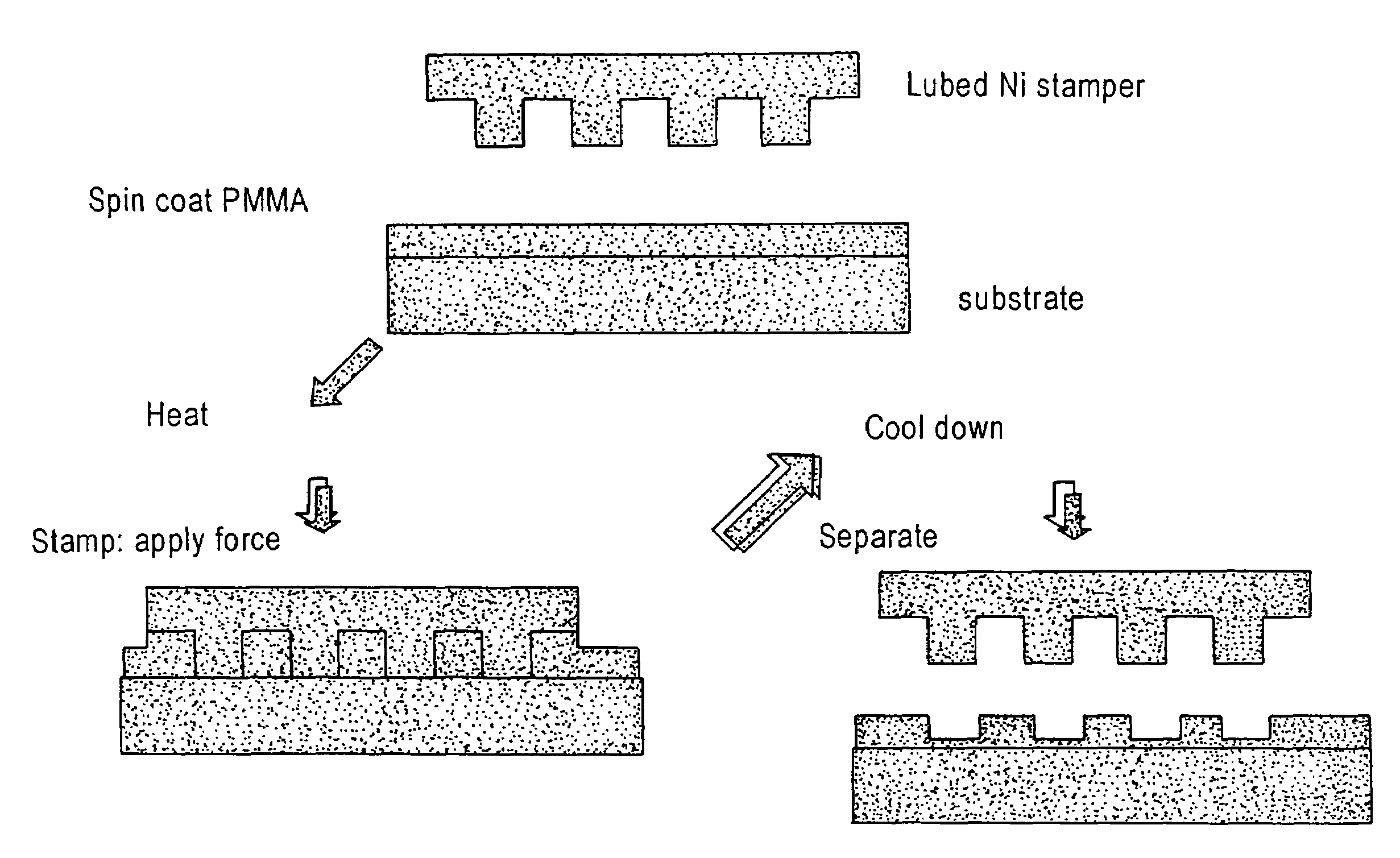
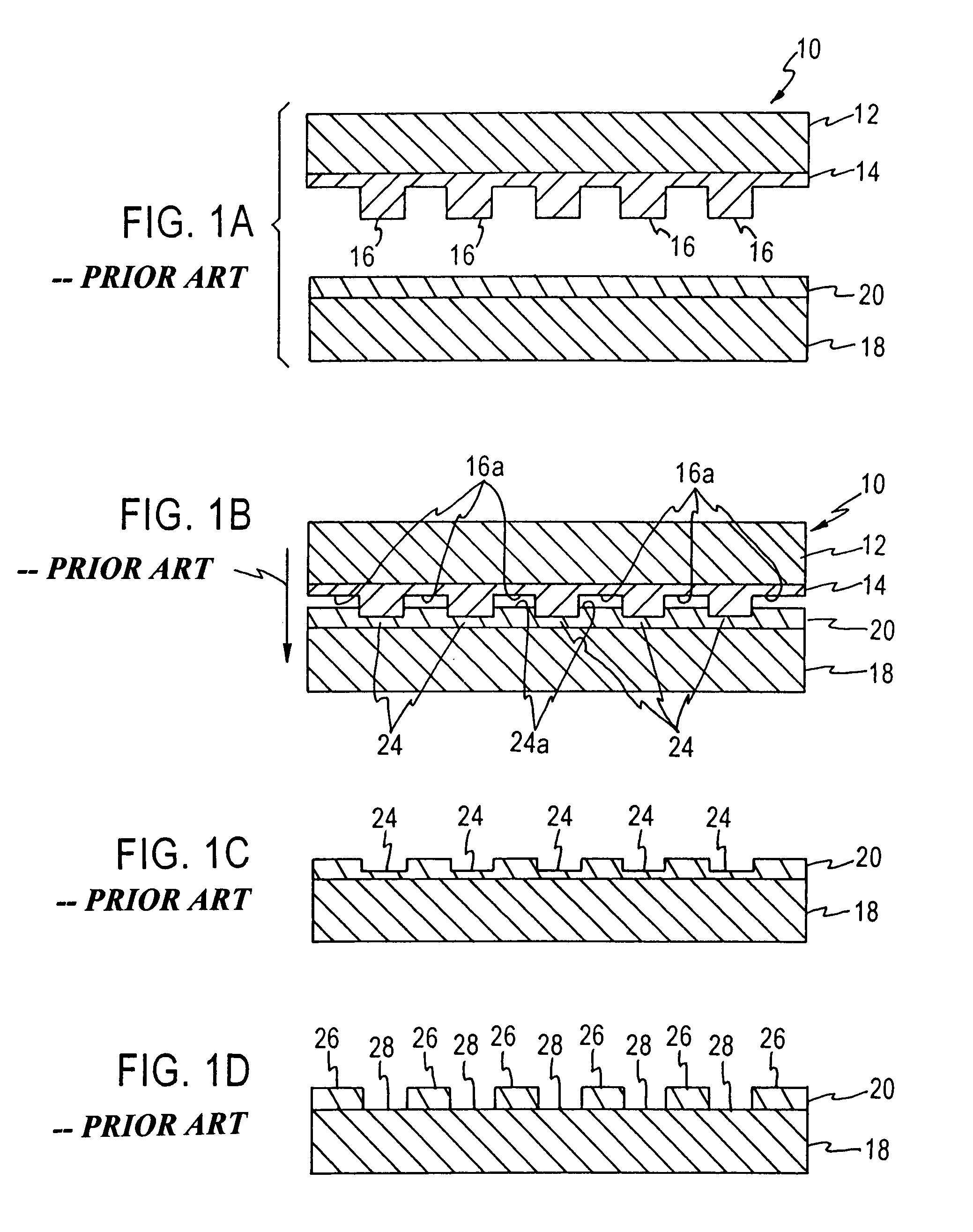
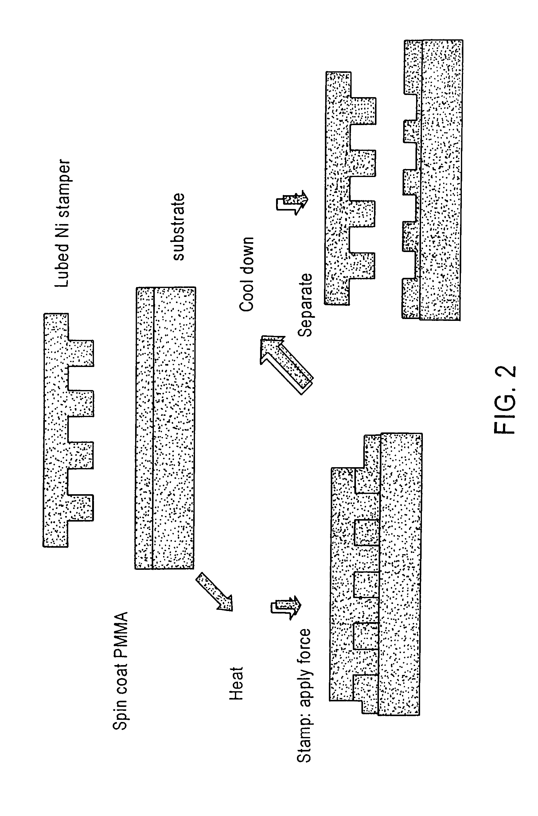
[0023]The present invention addresses and solves problems and difficulties such as degradation of replication quality due to resist deformation, peeling, and poor release, attendant upon the use of thermal imprint lithography for pattern definition in a workpiece surface. The present invention is particularly applicable to the fabrication of hard disk substrates with integrally formed servo patterns having sub-micron features, while maintaining automated manufacturing technology for pattern formation by imprint lithography. Further, the methodology and means afforded by the present invention enjoy diverse utility in the imprint lithographic patterning of a variety of substrates and workpieces.

[0024]The present invention addresses and solves problems attendant upon the use of a stamper and substrates in performing imprint lithography, e.g., nanoimprint lithography for forming submicron-dimensioned patterns and features in substrate surfaces used in magnetic recording media manufactur...


PUM

PropertyMeasurementUnit
thicknessaaaaaaaaaa
thicknessaaaaaaaaaa
depthsaaaaaaaaaa

Abstract

A method of performing imprint lithography of a surface substrate includes a stamper having a thin lubricant coating thereon to facilitate release of the stamper from the imprinted surface to reduce degradation of image replication. Embodiments of the invention include stampers suitable for use in patterning servo information on magnetic recording media having a lubricant coating of from about 1 nm to about 20 nm.

Description

CROSS-REFERENCE TO PROVISIONAL APPLICATIONS[0001]This application claims priority from U.S. provisional patent application Ser. No. 60 / 241,286, filed Oct. 17, 2000, the entire disclosure of which is incorporated herein by reference. This application contains subject matter similar to that disclosed in co-pending U.S. patent application Ser. No. 09 / 946,939, filed on Sep. 6, 2001.FIELD OF THE INVENTION[0002]The present invention relates to a stamper for forming sub-micron sized features and patterns in large area substrate surfaces by means of imprint lithography. The invention has particular utility in the formation of servo patterns in the surfaces of substrates used in the manufacture of information storage and retrieval media, e.g., hard disk magnetic recording media.BACKGROUND OF THE INVENTION[0003]Thermal imprint lithography has been recently studied and developed as a low cost alternative technique for patterning features in the surface of a substrate or workpiece, as for examp...

Claims


Application Information

Patent Timeline
Patent Type & Authority Patents(United States)
IPC IPC(8): B29C33/60
CPCB29C33/60B29C43/003B29C43/021B82Y10/00B82Y40/00G11B5/743G11B5/82G11B5/855G11B5/865G03F7/0002B29C2043/025Y10S425/81G11B7/263
Inventor WAGO, KOICHIGAUZNER, GENNADY
Owner SEAGATE TECH LLC
Why Eureka
Try Eureka