Channel-less proton exchange membrane fuel cell

a proton exchange membrane and fuel cell technology, applied in the field of electrochemical energy converters, can solve the problems of inadequate fluid distribution, incomplete fluid diffusion, and existing pemfcs, and achieve the effects of improving mechanical loading, superior mechanical loading, and facilitating electrical current transmission

Inactive Publication Date: 2007-11-13
TETROS INNOVATIONS LLC
View PDF12 Cites 10 Cited by
  • Summary
  • Abstract
  • Description
  • Claims
  • Application Information

AI Technical Summary

Benefits of technology

[0034]Another advantageous improvement over prior art PEMFCs exhibited by the present invention is its superior mechanical loading. Concluding the construction of PEMFC stack, the stack is mechanically loaded by one of several means. The mechanical loading of the fuel cell exerts pressure on all the components of the fuel cell, pressing them together in intimate contact with each other. The mechanically loaded state allows for the fluids to be contained within the fuel cell at high pressure without leaking to the external environment or leaking internally between fluid layers; the loaded state also facilitates the transmission of electrical current through the fuel cell. The present invention exhibits improved mechanical loading because the GDLs exhibit sufficient dimensional stability to support the internal pressure exerted under load.
[0035]The present fuel cell invention is similar to a monolithic block with internal features of very small size and thus very small unsupported span capable of compromising the structural integrity of the fuel cell. As an example of a preferred embodiment, the optimum GDL material situated over the active area of the fuel cell is only slightly less dense than carbon bipolar separators surrounding it, and is capable of bearing the same amount of mechanical loading pressure as the material around it; therefore the appropriate loading pressure is evenly distributed within the fuel cell without any fluid leaks. There are no unloaded channels or other internal features to cause an imbalance in the mechanical loading of the fuel cell. In this scenario, the fuel cell can be mechanically loaded with no adverse affects on the components.
[0036]The present fuel cell invention incorporating the GDLs having micro-channels material demonstrates superior fluid sealing, another advantageous improvement over the prior art PEMFCs. Fluid sealing is related to the mechanical loading improve

Problems solved by technology

Existing PEMFCs suffer from six significant problems: (1) inadequate fluid distribution, (2) incomplete fluid diffusion across the active area of the membrane, (3) electrical current transmission, (4) contact resistance, (5) inconsistent mechanical loading, and (6) insufficient fluid sealing.
These problems have precluded the PEMFC industry from mass-producing units of commercial utility.
These problems result from the structure of existing bipolar separators.
However, the macro-channels restrict the performance of the fuel cell because they distribute fluids to the active area only along the area that the channels traverse.
In addition, the macro-channels and macro-manifolds leave gaps in the volume of the fuel cell that are unable to transmit electrical current, seal the fluids, or support mechanical loading.
The fuel starvation of the underlying portions of the active area causes that specific portion of the active area to be either inactive, producing no electrochemical reactions, or restricted in the amount of electrochemical activity.
Thus, as the quantity of inactive and restrictive areas increase, the possible maximum power output of the fuel cell decreases.
This is a necessary process, but the macro-manifolds and macro-channels hamper fuel cell performance.
Therefore, areas not in direct contact with the macro channel may not receive sufficient fluid flow, such as those areas underneath the interstitial lands between the channels.
However, even with the use of GDLs, fluid distribution a

Method used


Image

  • Channel-less proton exchange membrane fuel cell
  • Channel-less proton exchange membrane fuel cell
  • Channel-less proton exchange membrane fuel cell

Examples


Embodiment Construction

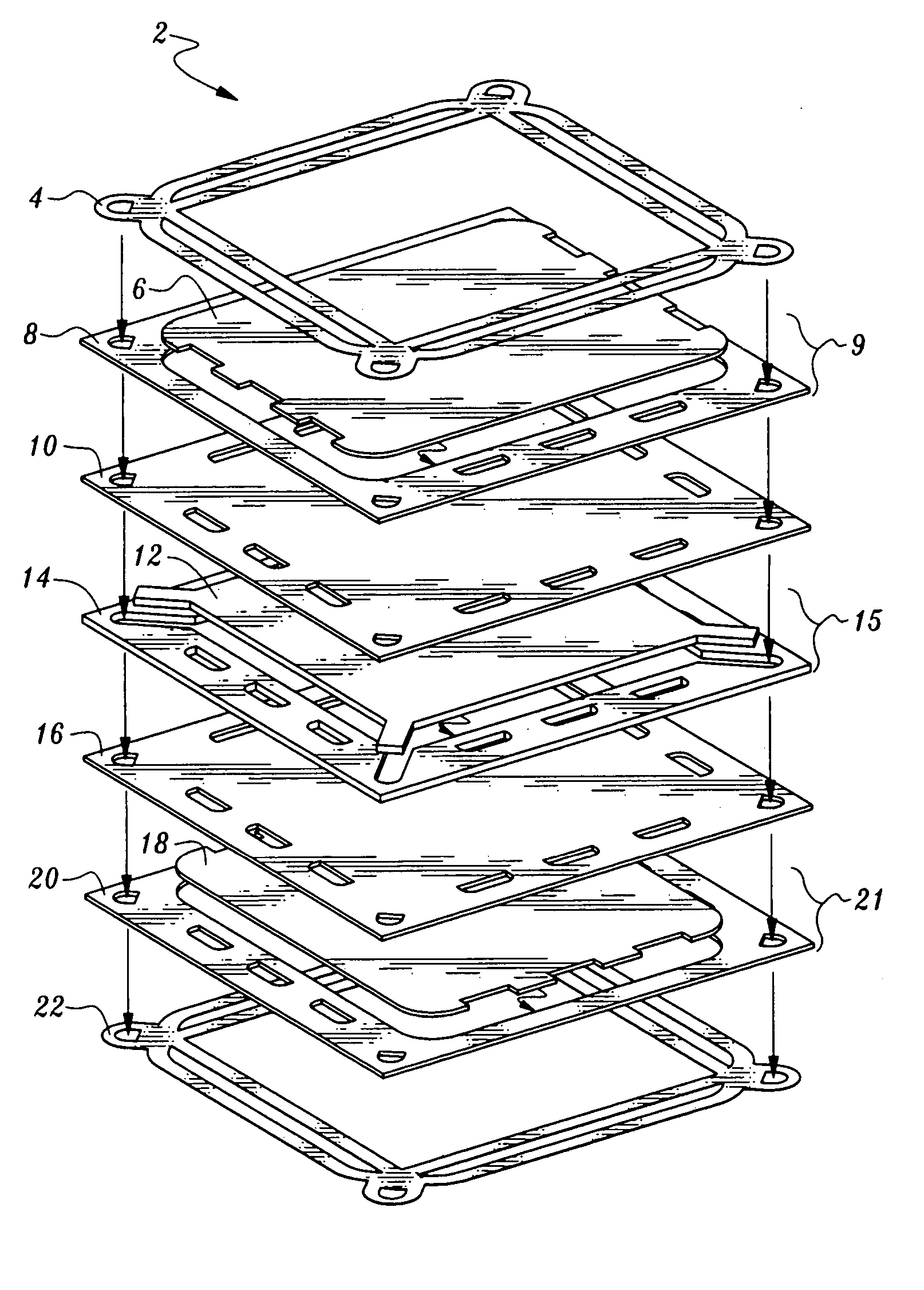
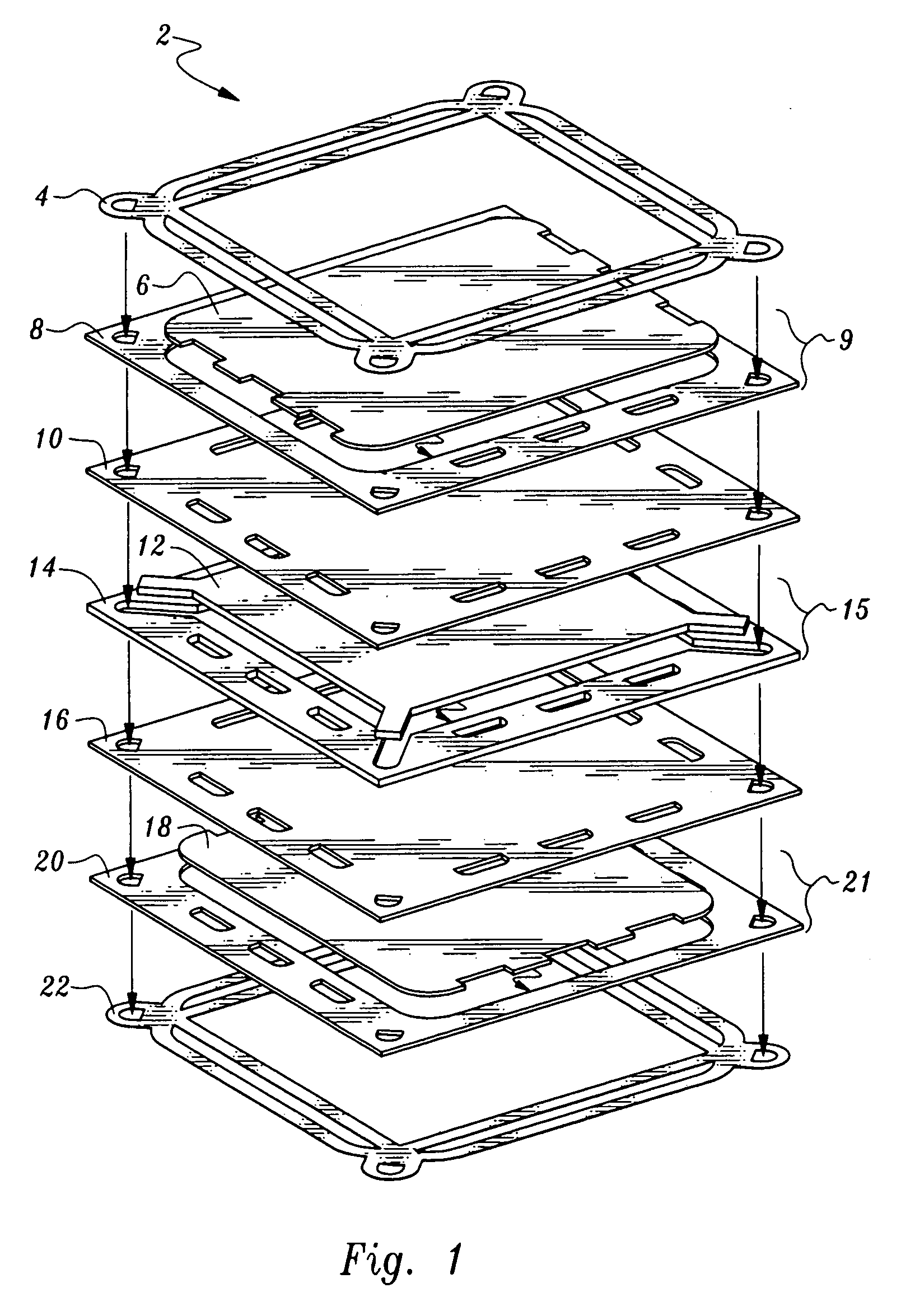
[0047]FIG. 1 shows an exploded isometric view of the preferred embodiment of bipolar separator 2. Bipolar separator 2 includes PTFE frame gasket 4, anode GDL 6, anode flow field gasket 8, blank gasket 10, coolant GDL 12, coolant flow field gasket 14, blank gasket 16, cathode GDL 18, cathode flow field gasket 20, and PTFE frame gasket 22. Anode GDL 6 and anode flow field gasket 8 together form anode separator 9; coolant GDL 12 and coolant flow field gasket 14 together form coolant separator 15; and cathode GDL 18 and cathode flow field gasket 20 together form cathode separator 21.

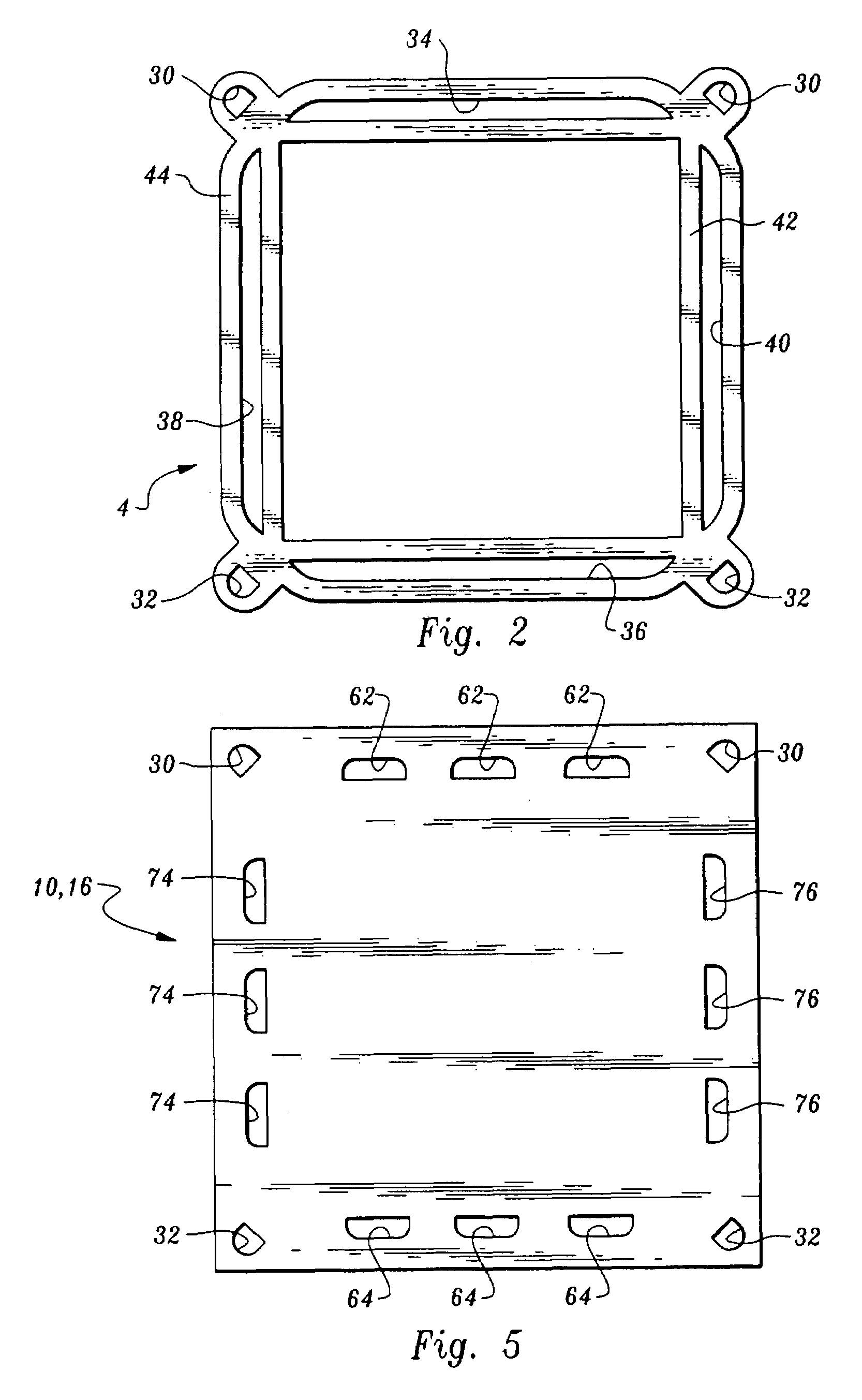
[0048]FIG. 2 is a detailed plan view of the obverse and reverse of PTFE frame gaskets 4 and 22. PTFE frame gaskets 4 and 22 include coolant ingress manifolds 30, coolant egress manifolds 32, PTFE oxidant ingress manifold 34, PTFEoxidant egress manifold 36, PTFE fuel ingress manifold 38, PTFE fuel egress manifold 40, inner sealing perimeter 42, and outer sealing perimeter 44. PTFE frame gaskets 4 and 22 funct...


PUM


Abstract

The present invention is a proton exchange membrane fuel cell that includes a fuel cell assembly. The fuel cell assembly includes a bipolar separator, which includes an anode separator, a cathode separator and a membrane electrode assembly. The bipolar separator includes a highly porous, electrically conductive, non-metallic interface and a non-porous frame. The highly porous interface includes micro-channels for fluid communication and diffusion. Both the cathodic interface and anodic interface of the bipolar separator contain the highly porous material in a fluid diffusion region that interfaces with the active area of the MEA interposed between two bipolar separators. The highly porous material connects the fluid diffusion regions with their respective external sources of oxidant and fuel. The bipolar separator includes a non-porous frame that seals the highly porous material and isolates the fluids within the proton exchange membrane fuel cell.

Description

CROSS-REFERENCE TO RELATED APPLICATION[0001]The present application claims the benefit of U.S. provisional patent application No. 60 / 436,107, filed Dec. 23, 2002 and entitled “Featureless Proton Exchange Membrane Fuel Cell,” which is hereby incorporated by reference.BACKGROUND OF THE INVENTION[0002]1. Field of the Invention[0003]The present invention relates to electrochemical energy converters such as fuel cells or electrolysis cells. More particularly, it relates to proton exchange membrane fuel cells (PEMFCs) that include a bipolar separator containing highly porous, electrically conductive, non-metallic material having micro-channels.[0004]2. Description of the Related Art[0005]Existing PEMFCs include a fuel cell assembly. The fuel cell assembly has three basic components: (1) an anode separator, (2) a cathode separator, (3) and a membrane electrode assembly (MEA) interposed between the anode separator and the cathode separator. The MEA consists of an ionomeric membrane with cat...

Claims


Application Information

Patent Timeline
IPC IPC(8): H01M2/00H01M2/02H01M2/14H01M2/08H01M4/94H01M8/02H01M8/10H01M8/24
CPCH01M8/023H01M8/0247H01M8/0273H01M8/242H01M8/0267H01M8/0234Y02E60/50H01M2008/1095
Inventor HODGE, REX A.COWGILL, LYN M.DOUARA, TAMER S.MILLER, MELISSA F.ORSBON, WYATT B.
Owner TETROS INNOVATIONS LLC
Why Eureka
Try Eureka