
Method of making carbon fiber-carbon matrix reinforced ceramic composites

a technology of carbon fiber and composites, applied in the field of carbon fiber-carbon-fiber matrix reinforced ceramic composites, can solve the problem of not having a uniform composition throughout the composition of metal carbide, and achieve the effect of more ductile and crack-free ceramic and aggressive diffusing

Inactive Publication Date: 2007-11-20
ULSTREETCARET
View PDF14 Cites 27 Cited by
  • Summary
  • Abstract
  • Description
  • Claims
  • Application Information

AI Technical Summary

Benefits of technology

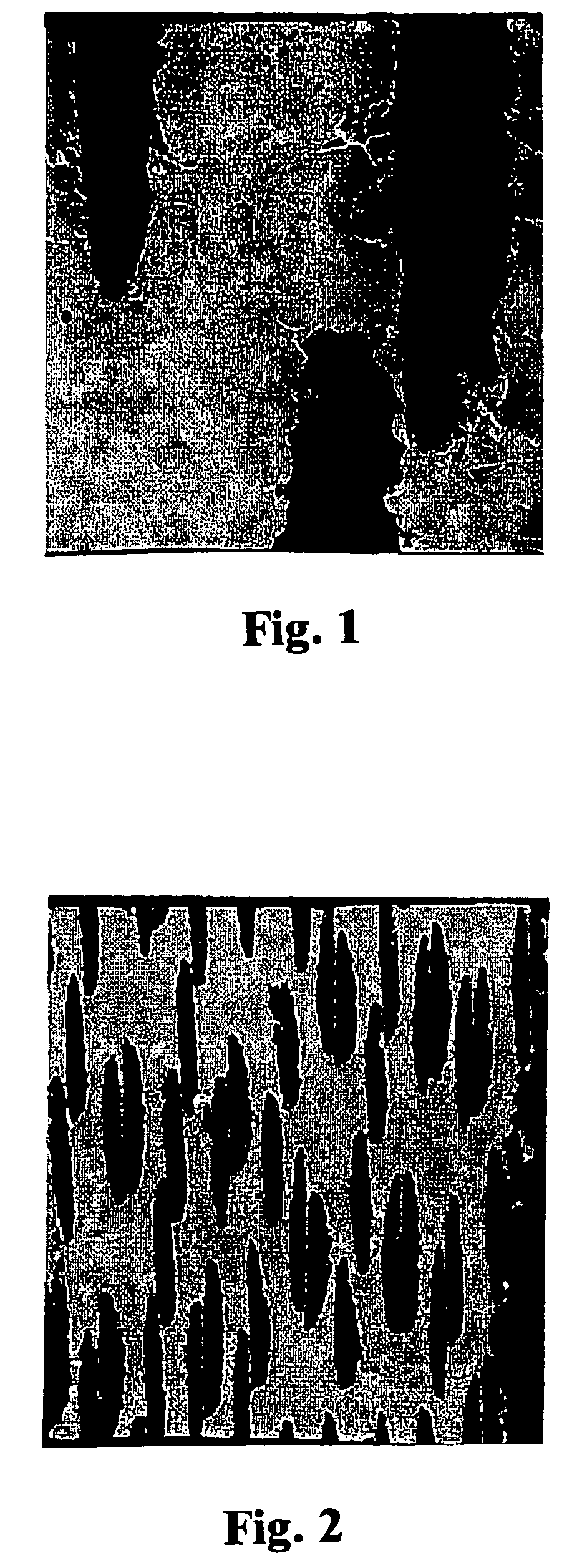
[0016]The ceramic matrix generally comprises a metallic carbide composition. The metal carbide composition is tailored to the particular end use to which the reinforced ceramic composite is to be put. Typically, the metal carbide composition does not have a uniform composition throughout. The embedded carbon fiber-carbon matrix composite reinforcements are preferably surrounded by metallic carbide layers or sheaths in which the ratio of metal to carbon is either carbon rich or near stoichiometric. The spaces between the reinforcement sheaths can be metal rich, silicon rich, or have about the same composition as the sheaths. Preferably, the carbide regions between the sheaths are metal rich so as to provide a more ductile and crack free ceramic. It has been found that the metal carbide layers or sheaths around the reinforcements protect them from attack by molten silicon. These sheaths are formed before the composite is exposed to molten silicon. Even though molten silicon is very aggressive in diffusing into carbon and in converting carbon to silicon carbide, it has been found that the preformed stoichiometric or carbon rich carbide sheaths adequately protect the carbon-carbon composite reinforcement from attack by the molten silicon.

Problems solved by technology

Typically, the metal carbide composition does not have a uniform composition throughout.

Method used


Image

  • Method of making carbon fiber-carbon matrix reinforced ceramic composites

Examples


Embodiment Construction

[0024]A preferred composite according to the present invention comprises a plurality of fiber bundles in the form of carbon fiber tows braided into a generally cylindrical combustion chamber preform having a length of about 8 inches, an inside diameter of about 2.5 inches, and an outside diameter of about 2.85 inches. Each of the tows contained from approximately 2000 to 3000 individual carbon fibers (or filaments) with an average diameter of about 10 microns.

[0025]The preform was subjected to a low temperature chemical vapor deposition process to form a dense continuous interface coating of zirconium oxide on each individual fiber. A standard vertically mounted quartz glass chemical vapor deposition reactor (8 inch outside diameter, 4 feet long with a wall thickness of about 2 millimeters) was equipped with a chlorination container loaded with 400 grams of zirconium metal turnings, and two ¼ inch stainless steel feed gas inlet tubes, one for oxygen and one for zirconium chloride. C...


PUM

PropertyMeasurementUnit
Percent by volumeaaaaaaaaaa
Volumeaaaaaaaaaa
Metallic bondaaaaaaaaaa

Abstract

A method of making a carbon fiber-carbon matrix reinforced ceramic composite wherein the result is a carbon fiber-carbon matrix reinforcement is embedded within a ceramic matrix. The ceramic matrix does not penetrate into the carbon fiber-carbon matrix reinforcement to any significant degree. The carbide matrix is a formed in situ solid carbide of at least one metal having a melting point above about 1850 degrees centigrade. At least when the composite is intended to operate between approximately 1500 and 2000 degrees centigrade for extended periods of time the solid carbide with the embedded reinforcement is formed first by reaction infiltration. Molten silicon is then diffused into the carbide. The molten silicon diffuses preferentially into the carbide matrix but not to any significant degree into the carbon-carbon reinforcement. Where the composite is intended to operate between approximately 2000 and 2700 degrees centigrade for extended periods of time such diffusion of molten silicon into the carbide is optional and generally preferred, but not essential.

Description

RELATED APPLICATIONS[0001]This application claims the benefit of U.S. Provisional Application Ser. No. 60 / 463,066, filed Apr. 15, 2003.STATEMENT REGARDING FEDERALLY SPONSORED RESEARCH OR DEVELOPMENT[0002]The U.S. Government has a paid-up license in this invention and the right in limited circumstances to require the patent owner to license others on reasonable terms as provided for by the terms of Contract No. NAS8-99093 awarded by NASA Marshall Space Flight Center (Huntsville, Ala.).BACKGROUND OF THE INVENTION[0003]1. Field of the Invention[0004]The invention relates in general to carbon fiber-carbon matrix reinforced ceramic composites and the production of such composites.[0005]2. Description of the Prior Art.[0006]Carbon fiber reinforced carbon matrix composites have been widely used for high temperature applications, particularly in military and aerospace applications. Such carbon reinforced carbon matrix composites have not achieved universal acceptance for such applications b...

Claims


Application Information

Patent Timeline
IPC IPC(8): C23C16/26C23C16/32C04B35/56C04B35/565C04B35/628C04B35/65C04B35/80C04B35/83
CPCC04B35/56C04B35/5622C04B35/62855C04B35/6286C04B35/65C04B35/806C04B35/83C04B2235/80C04B2235/404C04B2235/428C04B2235/5248C04B2235/5264C04B2235/614C04B35/80
Inventor WILLIAMS, BRIANBENANDER, ROBERT
Owner ULSTREETCARET
Learn More