Surface acoustic wave device and communication apparatus

a surface acoustic wave and communication apparatus technology, applied in the direction of electrical apparatus, impedence networks, piezoelectric/electrostrictive/magnetostrictive devices, etc., can solve the problems that the out-of-band attenuation characteristics of the conventional surface acoustic wave device cannot meet the foregoing requirements, and the quality of the received radio signal is degraded, so as to achieve superior communication quality, reduce the size of the communication apparatus, and reduce the effect of the effect of the effect of the effect o

Active Publication Date: 2007-11-20
KYOCERA CORP
View PDF21 Cites 34 Cited by
  • Summary
  • Abstract
  • Description
  • Claims
  • Application Information

AI Technical Summary

Benefits of technology

[0010]According to this configuration, the two filter elements can be formed on the same piezoelectric substrate, thereby making it possible to make the surface acoustic wave device smaller in size and make a mounting area on the circuit board smaller, as compared with those in a case where they are respectively formed on separate piezoelectric substrates. The out-of-band attenuation characteristics of the first filter element and the second filter element can be respectively reduced to desired values by providing the first and second via conductors for grounding the filter elements. Therefore, the surface acoustic wave device can be made high in reliability.
[0038]An unnecessary out-of-band signal can be sufficiently removed by using the high-frequency side filter element having good out-of-band attenuation characteristics for the receiving filter element, for example, thereby allowing the quality of a receiving signal to be improved. Further, a communication signal superior in quality can be transmitted without transmitting an unnecessary out-of-band signal by using the low-frequency side filter element having good out-of-band attenuation characteristics for the transmitting filter element, for example. Therefore, the communication apparatus can be made superior in power resistance.

Problems solved by technology

If the respective out-of-band attenuation characteristics of the transmitting filter element and the receiving filter element are degraded, an unnecessary radio signal is transmitted or received, thereby causing the possibilities that the quality of the received radio signal is degraded, and there arise problems such as interference with another radio communication apparatus.
The out-of-band attenuation characteristics of the conventional surface acoustic wave device cannot sufficiently cope with the foregoing requirements.

Method used


Image

  • Surface acoustic wave device and communication apparatus
  • Surface acoustic wave device and communication apparatus
  • Surface acoustic wave device and communication apparatus

Examples


examples

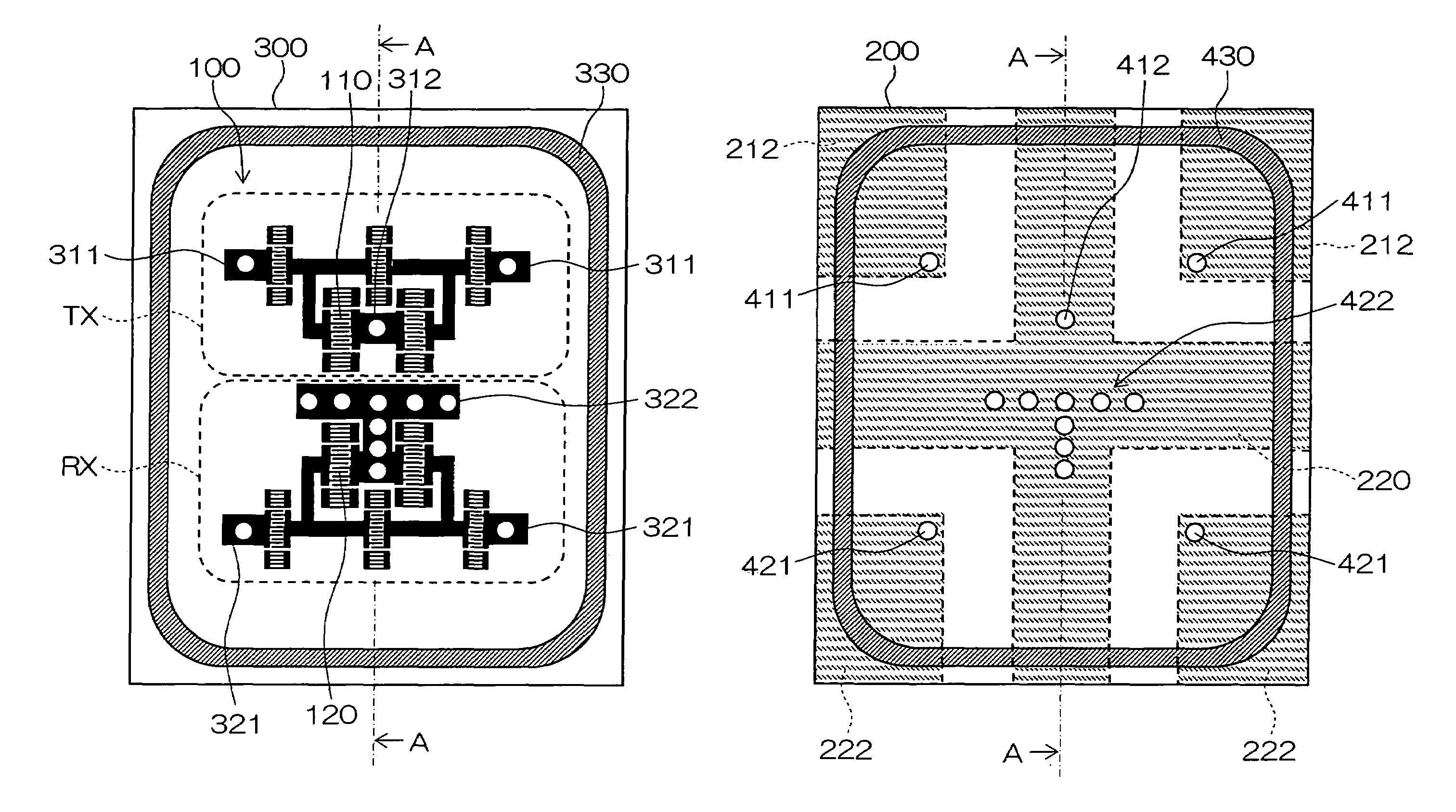
[0146]A surface acoustic wave device shown in FIGS. 7 and 8 was manufactured.

[0147]In a surface acoustic wave element, a 38.7-degree Y-cut X-propagation lithium tantalate single crystal substrate was used as a piezoelectric substrate, and IDT electrodes 110 and 120 composed of an Al alloy of Al (99% by mass)-Cu (1% by mass), ground electrodes 312 and 322, signal input / output electrodes 311 and 321, and a wiring electrode and a grounding annular electrode 330 for electrically connecting the electrodes were formed on its main surface.

[0148]The electrodes were produced by forming an Al alloy thin film using a sputtering method, then subjecting the thin film to photolithography using a spin-coater, a stepper, a developer, etc., etching the thin-film by the RIE (Reactive Ion Etching) apparatus, etc. to form predetermined patterns.

[0149]A circuit board was produced by laminating a plurality of insulating layers. Ceramics (a dielectric constant 9) mainly composed of alumina was used for th...


PUM


Abstract

In a surface acoustic wave device according to the present invention, a transmitting filter element TX and a receiving filter element RX are formed on one main surface of a piezoelectric substrate 300, and are mounted by face down on an upper surface of a circuit board 200. A ground electrode 322 in the receiving filter element RX is connected to three linear via conductors 221′ formed on the circuit board 200, and a ground electrode 312 in the transmitting filter element TX is connected to a crank-shaped via conductor 211′ formed on the circuit board 200.

Description

BACKGROUND OF THE INVENTION[0001]1. Field of the Invention[0002]The present invention relates to a surface acoustic wave device suitably employed for a filter element, a duplexer, and so forth and carrying a plurality of surface acoustic wave elements respectively having different frequency pass bands, and a communication apparatus comprising the surface acoustic wave device. The communication apparatus is employed for a mobile communication apparatus such as a cellular phone, for example.[0003]2. Description of Related Art[0004]In a communication apparatus such as a cellular phone, a surface acoustic wave device using a surface acoustic wave element comprising an IDT (Inter Digital Transducer) electrode as a duplexer for separating a transmission signal and a receiving signal. The surface acoustic wave device is a small in size, has steep filter element characteristics, and has superior properties such as superior mass productivity.[0005]Particularly in recent years, a small-sized ...

Claims


Application Information

Patent Timeline
Patent Type & Authority Patents(United States)
IPC IPC(8): H03H9/72H03H9/64
CPCH03H9/725H03H9/64H03H9/72
Inventor IKUTA, TAKANORIKOGA, WATARUYOKOTA, YUUKO
Owner KYOCERA CORP
Why Eureka
Try Eureka