Optical fiber assembly wrapped across gimbal axes

a technology of optical fiber and gimbal, which is applied in the direction of discharge tube/lamp details, direction controllers, instruments, etc., can solve the problems of unaccounted for optical paths, significant optical losses, and terrorists presenting a real threat to military aircraft and particularly commercial aircraft, etc., to achieve compact, light, and reliable

Active Publication Date: 2007-12-04
RAYTHEON CO
View PDF5 Cites 33 Cited by
  • Summary
  • Abstract
  • Description
  • Claims
  • Application Information

AI Technical Summary

Benefits of technology

[0010]The present invention provides a power efficient, reliable, compact, lightweight and inexpensive solution for optically coupling an off-gimbal optical source such as a laser beam to an on-gimbal optical element such as a telescope. The on-gimbal optical element can be mounted off the gimbal axis thereby preserving the central region of the gimbal for another optical path such as that used by a receiver. The technique can be adapted for gimbal motion in any one of the three axis of rotation, (e.g. roll, nod, and elevation) or any combination thereof. In the case of multi-axis rotation, the optical element is mounted on the innermost gimbal.
[0011]This invention uses a continuous optical fiber assembly (an optical fiber, one or more jackets around the fiber and a connector at each end of the fiber) that couples the off-gimbal optical source to the on-gimbal optical element. A fiber control mechanism routes the fiber assembly from the off-gimbal optical source across the gimbal axis / axes to the on-gimbal optical element so that the fiber assembly moves predictably with the rotation of the gimbal. For each gimbal, the control mechanism suitably pins one end of the fiber assembly off-gimbal and one end of the fiber assembly on-gimbal. Furthermore, the fiber assembly is suitably pinned as it crosses between gimbals so that the fiber assembly can move independently with each gimbal. The control mechanism routes the fiber assembly to (1) control the radius of curvature of the fiber assembly so as to be larger than a set minimum value to minimize stress on the delicate fiber, (2) accommodate the desired range of motion around each axis, (3) avoid entanglement and rubbing of the fiber assembly, (4) wrap the fiber assembly compactly around the gimbal and (5) avoid loading the gimbal motors. In multi-gimbal configurations, the fiber assembly may exhibit different mechanical stiffness as it cross the gimbal axes to accommodate varying mechanical requirements of the different gimbals.
[0012]In cases where a relatively large range of motion is required, the control mechanism is suitably configured to route the fiber assembly in a “U-shaped” loop with one end pinned off-gimbal in a stationary guide track and the other end pinned on-gimbal point in a rotating guide track so that loose fiber assembly is constrained in the concentric tracks on and off gimbal. As the gimbal rotates the loop seats onto one guiding track and peels off of the other guiding track while always maintaining its U shape. This embodiment maintains a minimum set radius of curvature, accommodates any range of motion only limited by the length of the fiber assembly, and keeps the fiber assembly compactly wound in the guide tracks where it cannot become entangled with the gimbal or other elements.
[0013]In other cases where a relatively small range of motion is required, the control mechanism is suitably configured to pin one end of the fiber assembly off-gimbal and pass the fiber assembly directly over the gimbal where it is pinned on the other side of the gimbal. The control mechanism routes the fiber assembly so that it maintains the minimum radius of curvature, does not rub against the nod gimbal and is not too stiff so as to burden the nod motor.
[0014]In an exemplary embodiment, a pointer for use in a DIRCM system includes a roll-nod gimbal having a receiver centrally located on the nod gimbal along the optical axis. The roll-nod gimbal slews to point the optical axis at an incoming missile to receive and track its IR signature. A continuous optical fiber assembly carries a laser beam from an off-gimbal laser across the roll-nod axes to a telescope mounted off-axis on the nod (innermost) gimbal. The telescope directs the laser beam at and jams the threat missile's IR seeker. Because the laser energy does not pass through the gimbal axes, the transmission of laser energy is decoupled from restrictions imposed by the receiver's free space optics and coupling methods. Different off-gimbal sources may be coupled to one or more telescopes on the nod gimbal using a plurality of fiber assemblies, using a single fiber assembly including a plurality of fibers or by coupling the laser beams into a single fiber. A fiber control mechanism routes the fiber assembly in a “U-shaped” loop around the roll axis with one end pinned off-gimbal and the other end pinned to the roll gimbal so that the loose fiber assembly is constrained in concentric guide tracks on and off gimbal. As the roll gimbal rotates, the loop seats onto one guide track and peels off of the other guide track while always maintaining its U shape. The fiber control mechanism then passes the pinned fiber assembly directly over the nod gimbal where it is pinned on the other side of the gimbal. To improve performance, the entire fiber assembly suitably may include a pliable inner jacket that allows the fiber to move flexibly over the nod gimbal. The portion of the fiber that forms the U loop (or the entire fiber) may be suitably provided with a stiffer intermediate jacket that presses the fiber into the guide tracks. The portion of the fiber assembly between the roll-nod gimbal and the off-gimbal laser suitably includes a protective outer jacket. As a result, the jacketed fiber exhibits different mechanical properties as it crosses over the gimbal and nod axes.

Problems solved by technology

The proliferation of shoulder-launched missiles known as MANPADS for “Man-Portable Air-Defense System” and their availability to terrorists present a real threat to military aircraft and particularly commercial aircraft.
More than half a million MANPADS have been delivered worldwide, and many of these are unaccounted for in legitimate inventories.
The optical path has significant optical losses, which reduces the output power of the modulated laser.
Furthermore, the air-glass interfaces of the free-space components are highly susceptible to contamination and damage, which reduces the reliability of the system.
In addition, the LAIRCM system can not support an additional UV laser to counter more advanced threats because the internal optics and transmit ports do not transmit UV.
Each air gap is subject to contamination and, as experienced during the demonstration, damage to the AR coatings.
It was found that even at the modest power levels used in the BAE demonstration the high peak optical power from the laser caused damage to the AR coatings.
However, the fibers were undamaged and continued to transmit the laser power.
The rotary joints also introduce additional loading on the gimbal torquers resulting in reduced slew rates and increased settling times. This adversely impacted system performance, especially in multiple short shot engagements.
The rotary joint limits any attempt to significantly downsize the gimbal to reduce aerodynamic drag due to mechanical limitations inherent in the design of the rotary joint, fiber fittings and fiber protective sheathing which limit fiber bend radius on each side of the fiber optic rotary joint.
ion. This spool structure is a complex mechanical structure that is likely to have reliability problems and also suffers from an excess of optical f
iber. This extra length translates into extra optical losses of 0.2-1 dB per meter for a laser beam guided through the f

Method used


Image

  • Optical fiber assembly wrapped across gimbal axes
  • Optical fiber assembly wrapped across gimbal axes
  • Optical fiber assembly wrapped across gimbal axes

Examples


Embodiment Construction

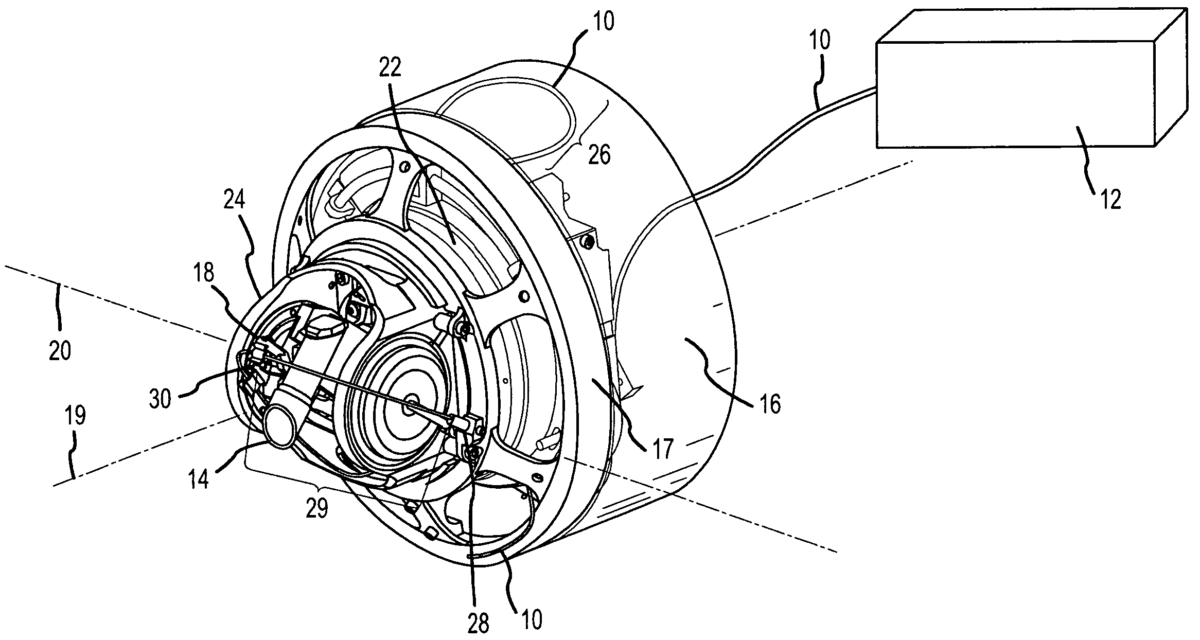
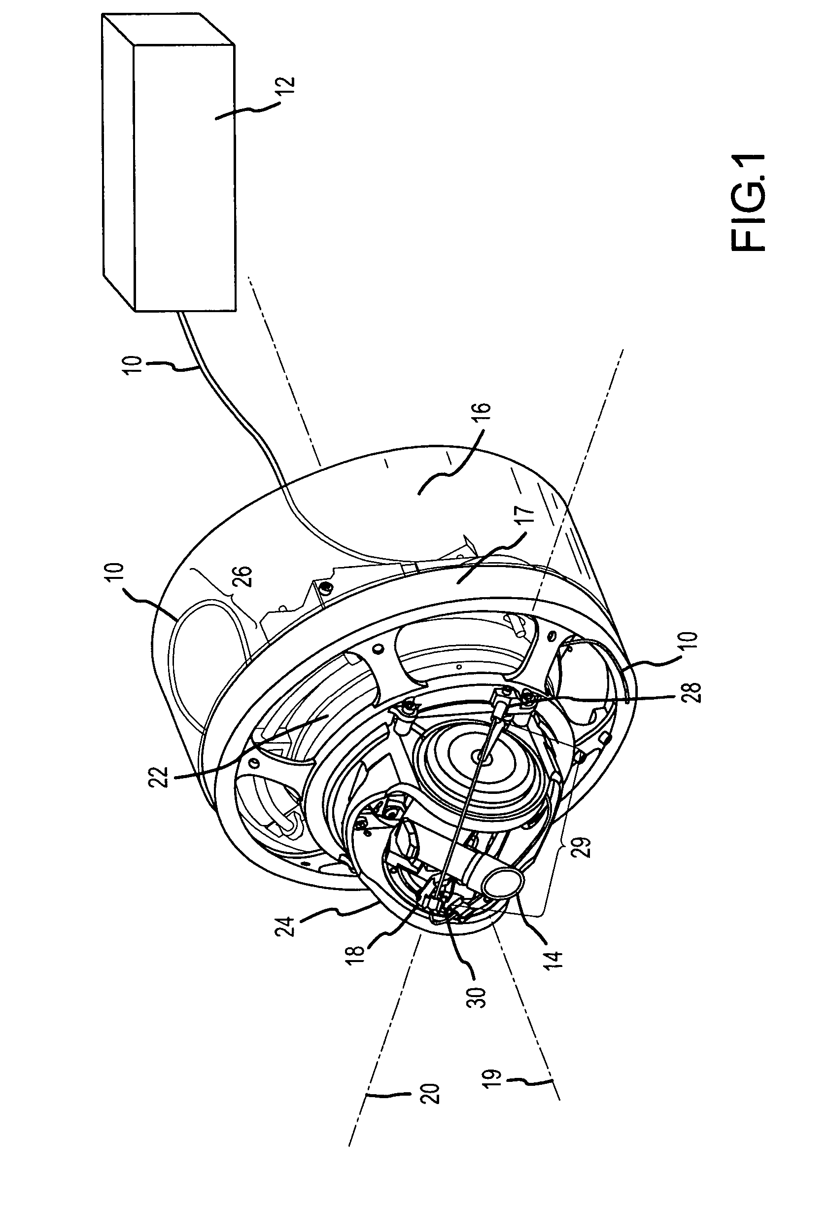
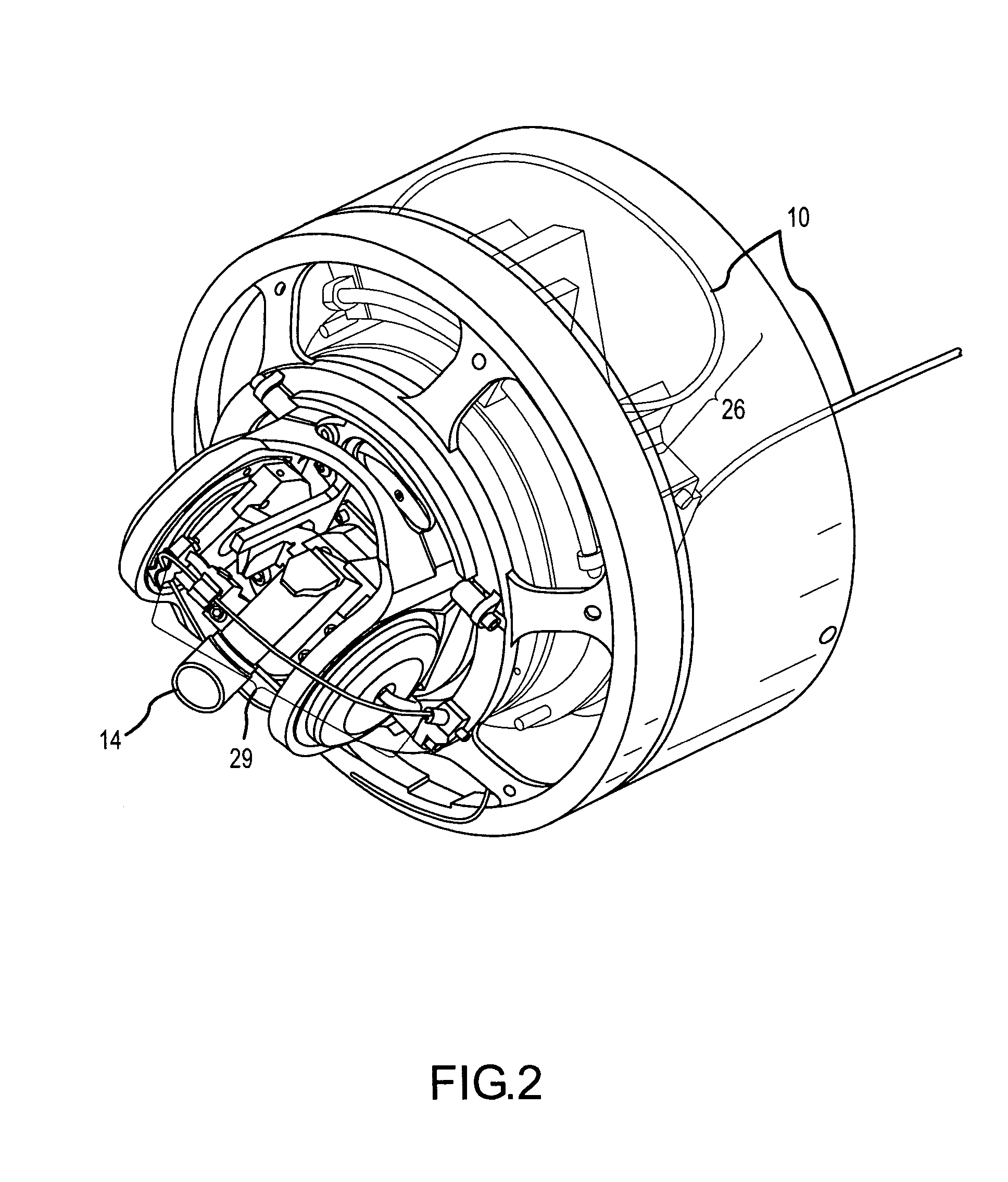
[0024]The present invention provides a power efficient, reliable, compact, lightweight and inexpensive solution for optically coupling an off-gimbal optical source such as a laser beam to an on-gimbal optical element such as a telescope. The on-gimbal optical element can be mounted off-axis thereby preserving the central region of the gimbal for another optical path such as that used by a receiver. The technique can be adapted for gimbal motion in any one of the three axis of rotation, (e.g. roll, nod, and elevation) or any combination thereof. In the case of multi-axis rotation, the optical element is mounted on the innermost gimbal. For clarity we will use a roll-nod gimbal throughout to illustrate the invention. Throughout the description we refer to pinning an “end” of the fiber assembly on or off gimbal. The “end” is actually a point along the continuous fiber, and is only an “end” with respect to the particular gimbal that is being described. The true ends of the fiber are cou...


PUM


Abstract

A control mechanism pins an optical fiber assembly on and off gimbal and between gimbals to route the assembly from an off-gimbal optical source across the gimbal axis / axes to an on-gimbal optical element so that the fiber assembly moves with the rotation of the gimbals. To accommodate a relatively large range of motion, the control mechanism is suitably configured to route the fiber assembly in a “U-shaped” loop with one end pinned off-gimbal in a stationary guide track and the other end pinned on-gimbal point in a rotating guide track so that the loose fiber assembly is constrained in the concentric tracks on and off gimbal. As the gimbal rotates, the loop seats onto one guiding track and peels off of the other guiding track while always maintaining its U shape. To accommodate a relatively small range of motion in other gimbal configurations, the control mechanism is suitably configured to pin one end of the fiber assembly off-gimbal and pass the fiber assembly directly over the gimbal where it is pinned on the other side of the gimbal. In a multi-gimbal pointer, the fiber assembly preferably exhibits different mechanical stresses as it crosses the different gimbals.

Description

BACKGROUND OF THE INVENTION[0001]1. Field of the Invention[0002]This invention relates to optical gimbals, and more particularly to the use of an optical fiber assembly wrapped across the gimbal axes to couple an off-gimbal light source to a telescope mounted on the innermost gimbal. The invention is particularly useful in Directed Infrared Countermeasures (DIRCM) systems that employ roll-nod gimbaled pointers to receive infrared (IR) radiation that is used to detect and track missiles and to transmit one or more infrared (IR) laser beams that are used to jam the seeker of a threatening IR-guided missile.[0003]2. Description of the Related Art[0004]The proliferation of shoulder-launched missiles known as MANPADS for “Man-Portable Air-Defense System” and their availability to terrorists present a real threat to military aircraft and particularly commercial aircraft. Estimates of the number of attacks on commercial aircraft vary, running as high as 43 hits on civilian aircraft—with 30...

Claims


Application Information

Patent Timeline
Patent Type & Authority Patents(United States)
IPC IPC(8): F41G7/00
CPCF41G7/224G01S7/495G01S7/4818F41H13/0056
Inventor MILLS, JAMES P.GARRETT, DAVID G.SUNNE, WAYNE L.KNAPP, DAVID J.BRUNTON, DANIEL W.ANTHONY, DAVID G.ANDERSON, EMMET R.HARRISON, DANIEL C.SMITH, III, FRANK E.HICKS, JIM R.
Owner RAYTHEON CO
Why Eureka
Try Eureka