
Optical waveguide and method for producing same

a technology of optical waveguides and optical fibers, applied in the field of optical waveguides, can solve the problems of device complexity, cost versus effect, and not yet spread, and achieve the effect of ensuring high light propagation characteristics

Inactive Publication Date: 2007-12-11
SONY GRP CORP
View PDF9 Cites 46 Cited by
  • Summary
  • Abstract
  • Description
  • Claims
  • Application Information

AI Technical Summary

Benefits of technology

This approach allows for high-speed signal transmission with reduced electromagnetic noise and propagation delay, enabling the use of cost-effective substrates and maintaining high light propagation characteristics, thus overcoming the limitations of traditional methods.

Problems solved by technology

Recently, although optical fiber channels and optical data links and other technology for using optical transmission have begun spreading in use, at the present time they have not yet spread to an extent of the optical communications and transmitting means replacing wired communications and transmitting means.
One of the reasons for this is the issue of cost versus effect.
Specifically, for example, there can be mentioned the points that, in order to maintain the performance of optical communications (for example, transmission rate and transmission quality), technology is required for precise positioning between a light emitting element and a light receiving element constituting the optical communications device and the optical fiber, that countermeasures for light leakage, consideration of electromagnetic interference, and countermeasures to noise are necessary, and that, as a result, the device becomes complex and expensive etc.
Accordingly, the issues have arisen of how to deal with the rise in the frequency of the signal processing clocks, the rise in the degree of parallel operation, and the rise in the speed of the access to the memories.
In memory access circuits and processors of multi-microprocessor (MPU) configurations, however, the parasitic capacitance component of the portion which becomes necessary at the time of mounting, for example, the package of the semiconductor device, is large, so high speed signal transmission operation becomes difficult in the electric wiring connected to the outside of the semiconductor chips.
Further, application of a high speed signal to the electric wiring can cause spikes in the current or the voltage and can cause electromagnetic interference (EMI) and other types of electromagnetic interference noise, reflection noise, and crosstalk noise.
Formation of the optical waveguide path 502 using thin film technology results in an excellent dimensional accuracy, but conversely has the disadvantage that the formation and processing of a film having a thickness of no more than several μm are difficult.
For this reason, it suffers from the disadvantage that while it is essential to form the thin film multilayer wiring 505 as the electrical wiring on the silicon substrate 501, this electrical wiring forming region would be too costly and poor in practicality if being the usual circuit board size (several 10s of cm square) or module size (several cm square).
The surface of a circuit board fabricated by such a thick film process, however, has thick films of metal formed by for example a plating process and therefore has a large unevenness.
For this reason, if the optical waveguide path is formed on such a printed circuit board, the disadvantage arises that the uneven shape of the surface of the board will end up having an effect on the shape of the optical waveguide path and end up leading to an increase of the light propagation loss of the optical waveguide path and a reduction of the dimensional accuracy.
Further, in the wet etching or washing etc. when forming the optical waveguide path on a circuit board, a step of immersing the entire board in acidic and alkaline solutions or organic solvents or the like becomes necessary, therefore there is the problem of the board being liable to be damaged.
Further, the board is also liable to be damaged at the time of dry etching or the time of the high temperature heat treatment.
Accordingly, it is difficult to use a circuit board formed by the thick film process as the substrate, so it was necessary to use an expensive substrate having a high heat resistance and other characteristics.

Method used


Image

  • Optical waveguide and method for producing same
  • Optical waveguide and method for producing same
  • Optical waveguide and method for producing same

Examples


first embodiment

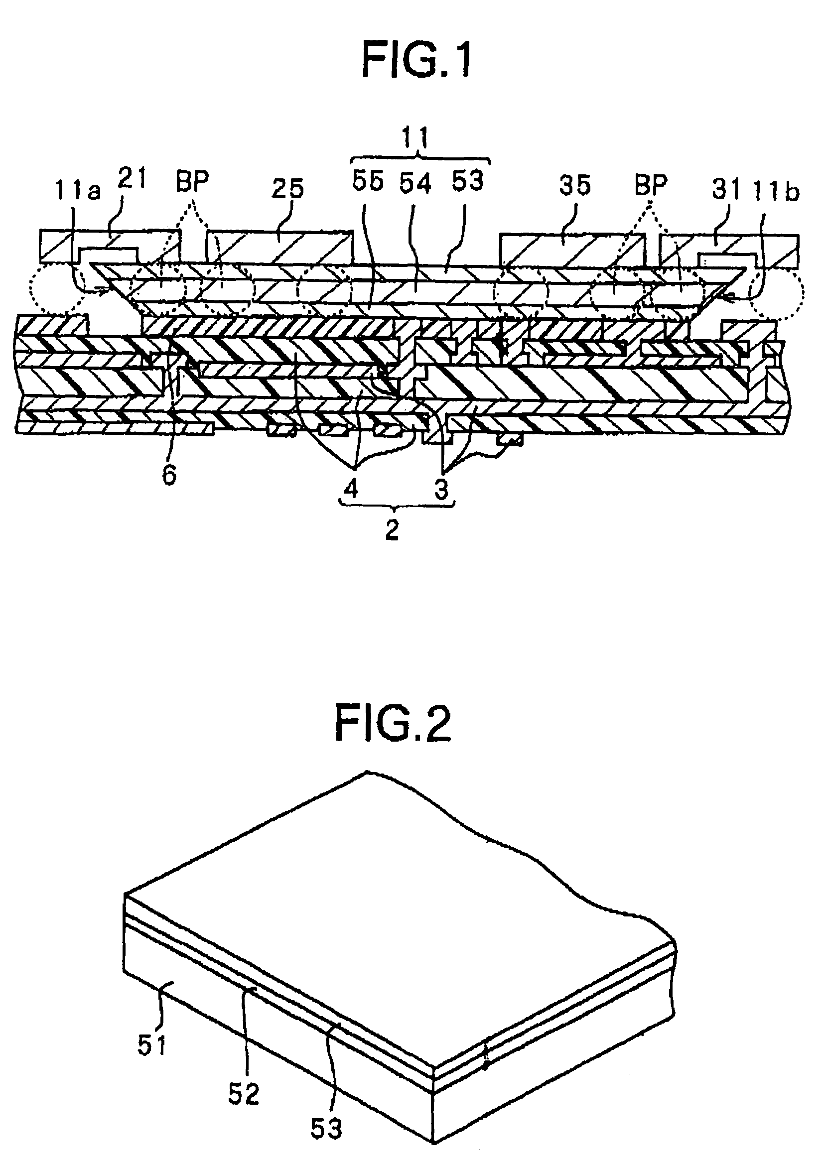
[0118]First, an explanation will be made of the configuration of an optical waveguide according to a first embodiment of the present invention with reference to FIG. 1.

[0119]FIG. 1 is a view showing the sectional configuration of an optical waveguide 1 according to the present embodiment. This optical waveguide 1 is provided with a multilayer circuit board 2, an optical waveguide path 11 bonded to the multilayer circuit board 2 via a bonding layer 6, a light receiving element 21 mounted on the multilayer circuit board 2 over the optical waveguide path 11 as a spacer, IC chips 25 and 35, and a light emitting element 31. Here, the multilayer circuit board 2 corresponds to a concrete example of the “substrate” and “second substrate” of the present invention. Further, the IC chips 25 and 35 correspond to concrete examples of the “integrated circuit” of the present invention.

[0120]The multilayer circuit board 2 is an electric circuit substrate comprised of a plurality of electrical wirin...

second embodiment

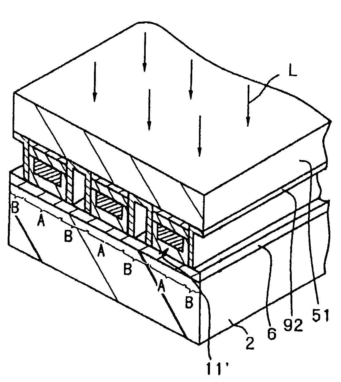
[0153]The second embodiment relates to a method for producing the optical waveguide. The optical waveguide covered by this method is similar to that of the first embodiment except for the point that the optical waveguide paths are spaced from each other. Below, an explanation will be made of the method for producing the optical waveguide of the present embodiment by referring to FIG. 1 through FIGS. 5A and 5B and FIG. 13 through FIG. 20. FIG. 13 through FIG. 20 are partially cutaway perspective views representing steps of production. Note that constituent elements the same as those of the first embodiment are given the same reference numerals and detailed explanations thereof are omitted.

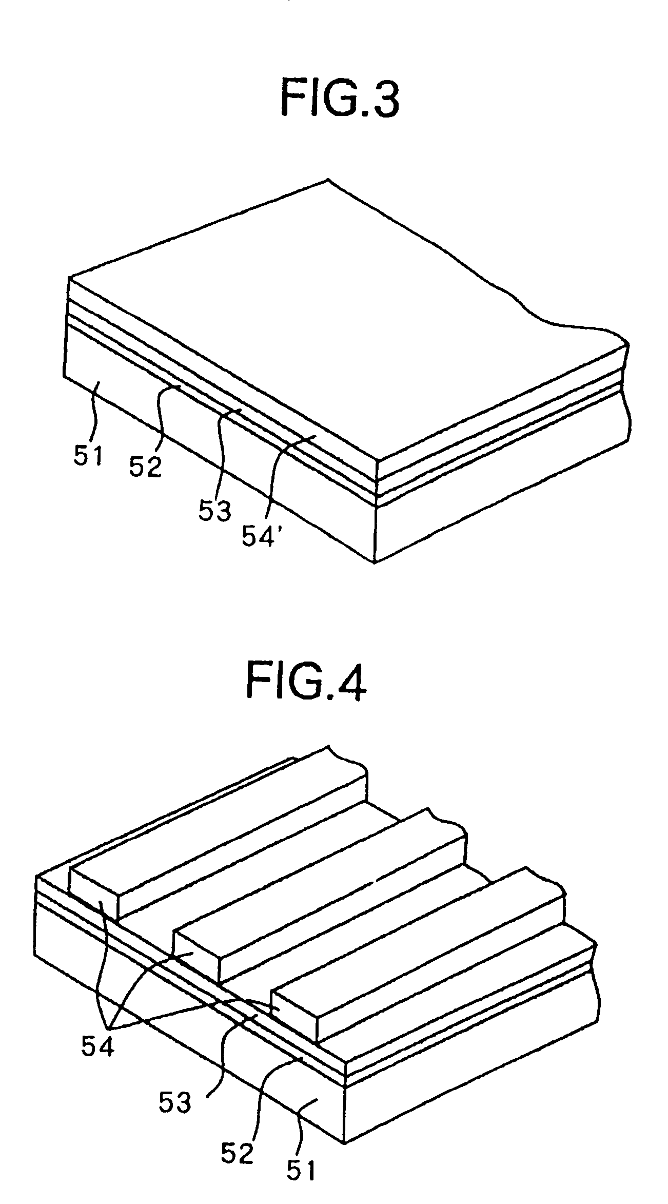
[0154]In the method of production according to the present embodiment, first, in the same way as the steps of productions shown in FIG. 2 to FIGS. 5A to 5B of the first embodiment, the substrate separation layer 52 and the optical waveguide path 11 are formed on a transparent substrate 51.

[0155]Next...

third embodiment

[0165]The third embodiment of the present invention relates to a method for producing a optical waveguide path. The structure of the optical waveguide covered by the method is similar to that shown in FIG. 1. The method for producing the optical waveguide according to the present embodiment is similar to that of the first embodiment except for the point that the method for forming the inclined surfaces 11a and 11b of the optical waveguide path 11 is different. Below, the explanation will be made by referring to FIG. 21 through FIG. 23. Note that constituent elements the same as those of the first embodiment are given the same reference numerals and detailed explanations thereof are omitted.

[0166]In the method for forming the inclined surfaces of the present embodiment, first, as shown in FIG. 21, an optical waveguide path 11 comprising the upper cladding layer 53, core layer 54, and the lower cladding layer 55 is formed on a transparent substrate 51 via the substrate separation laye...


PUM


Abstract

An optical waveguide having a optical waveguide path capable of securing a high light propagation characteristic regardless of the type of a supporting base, provided with a multilayer circuit board, an optical waveguide path arranged on the multilayer circuit board, a light receiving element, IC chips, and a light emitting element, the optical waveguide path formed on a transparent substrate excellent in flatness and transferred to the multilayer circuit board. The light propagation loss becomes small, and a signal to be transmitted at a high speed being transmitted as a light signal and a signal which can be transmitted at a relatively low speed being transmitted as an electrical signal, whereby the signal propagation delay which becomes the problem when a signal is transmitted by only electrical wiring is overcome, and the influence of electromagnetic noise becomes small.

Description

RELATED APPLICATION DATA[0001]The present application claims priority to Japanese Application No. P 10-306090, filed Oct. 27, 1998, and Japanese Application No. P11-120631, filed Apr. 27, 1999, and is a divisional of U.S. application Ser. No. 10 / 301,008 filed Nov. 21, 2002 now U.S. Pat. No. 7,163,598, which application is a divisional of U.S. application Ser. No. 09 / 422,255, filed Oct. 21, 1999 now abandoned, all of which are incorporated herein by reference to the extent permitted by law.BACKGROUND OF THE INVENTION[0002]1. Field of the Invention[0003]The present invention relates to an optical waveguide provided with an optical waveguide path through the inside of which a light signal is propagated and a method for producing the same, more particularly relates to a optical waveguide suitable for transmitting a light signal in an ultra high speed signal processing circuit or parallel type digital signal processing circuit or other signal processing circuit, optical communication, an...

Claims


Application Information

Patent Timeline
Patent Type & Authority Patents(United States)
IPC IPC(8): B44C1/18G02B6/036G02B6/122B44C1/24G02B6/136G02B6/12G02B6/13H01S5/00H01S5/026
CPCG02B6/13Y10T428/2804Y10T428/24868G02B6/12
Inventor OKUBORA, AKIHIKOOGAWA, TSUYOSHI
Owner SONY GRP CORP
Learn More