Vanadium/polyhalide redox flow battery

a technology of redox flow cells and polyhalide, which is applied in the direction of indirect fuel cells, non-aqueous electrolyte cells, cell components, etc., can solve the problems of limited application in some fields unsuitable use of aqueous hydrochloric acid, etc., and achieve the effect of reducing potential cross-contamination

Inactive Publication Date: 2008-01-22
WATTJOULE
View PDF9 Cites 61 Cited by
  • Summary
  • Abstract
  • Description
  • Claims
  • Application Information

AI Technical Summary

Benefits of technology

[0017]In a preferred redox flow cell according to the present invention the electrolyte in the negative half-cell comprises VCl2 and/or VCl3 dissolved in a supporting electrolyte, and the electrolyte in the positive half-cell comprises ClBr2−/Br− and/or BrCl2−/Cl− redox couples in a supporting electrolyte. For such a redox flow cell, it is preferred that the supporting electrolyte in both half-cells is selected from aqueous solutions of HCl, a mixture of NaCl and HCl, a mixture of KCl and HCl, or mixtures thereof. In an alternative preferred redox flow cell according to the present invention, the electrolyte in the negative half-cell comprises VBr3 and/or VB

Problems solved by technology

While the performance characteristics of the all-vanadium redox flow cell have made it well suited to various stationary applications, its relatively low energy density has to date limited its application in some fields, for example, in electric ve

Method used


Image

  • Vanadium/polyhalide redox flow battery
  • Vanadium/polyhalide redox flow battery
  • Vanadium/polyhalide redox flow battery

Examples


example 1

[0061]Experiments were conducted to examine the electrochemical reversibility of the V(III) / V(II) redox couple in different concentrations of chloride ions in aqueous HCl.

[0062]FIG. 3 shows a series of cyclic voltamograms obtained at a graphite electrode in solutions containing 2.02 M VCl2 in various concentrations of total Cl− ((A) 5.08 M Cl−, (B) 6.68 Cl− and (C) 8.48 M Cl−). The X axis shows the electrode potential in volts versus the saturated calomel electrode (SCE). Increasing the chloride ion concentration appears to shift the peak potentials, but an anodic peak is observed at a potential of around −0.75 V in the solution containing 8.48 M total Cl− ions while the corresponding cathodic peak appears at approximately −1.07. V. The formal potential of the V(III) / V(II) redox couple is thus seen to be at around −0.95V, which is very suitable for use in the negative half-cell of a redox flow battery. Another favourable feature is the absence of any significant hydrogen evolution c...

example 2

[0063]A series of cyclic voltamograms were obtained in aqueous solutions of 0.1 M HCl, 1.0 M HCl+0.27 M NaBr and 1.0 M HCl+2.5 M NaBr. The results are shown in FIG. 4. From the lower curve (1.0 M HCl) it can be seen that scanning the electrode in the positive direction, gives rise to an anodic current associated with Cl2 and / or O2 evolution. No cathodic peak is observed on reserving the scan potential, thus showing no electrochemically reversible products are produced at the electrode surface during the positive scan. However, when NaBr is present in the electrolyte, anodic and cathodic peaks appear in the forward and reverse scans respectively, showing that a reversible redox couple reaction with a formal potential of approximately 0.85 V versus SCE, is occurring at the electrode (middle curve). When the concentration of the NaBr is increased to 2.5 M (top curve), the height of the anodic peak increases significantly, showing that the Br− ions are in fact oxidised at the electrode ...

example 3

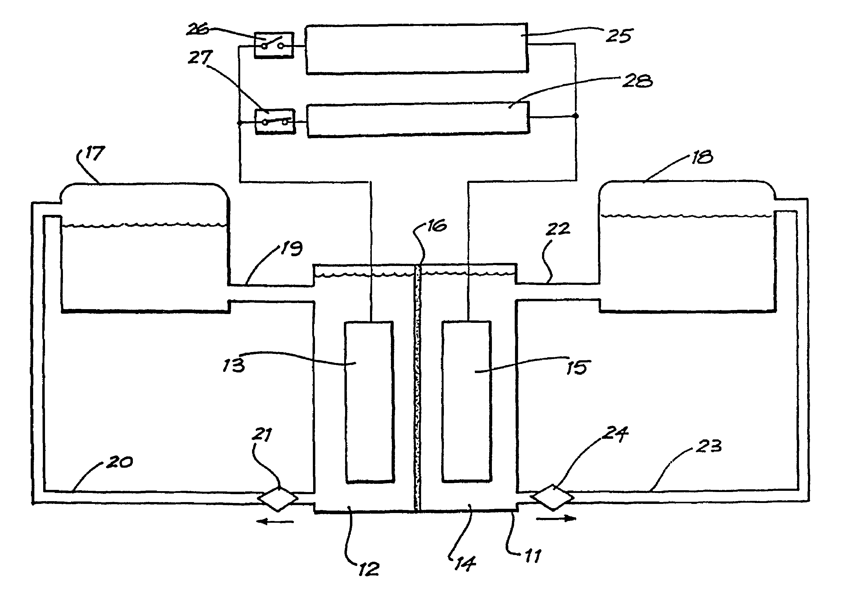
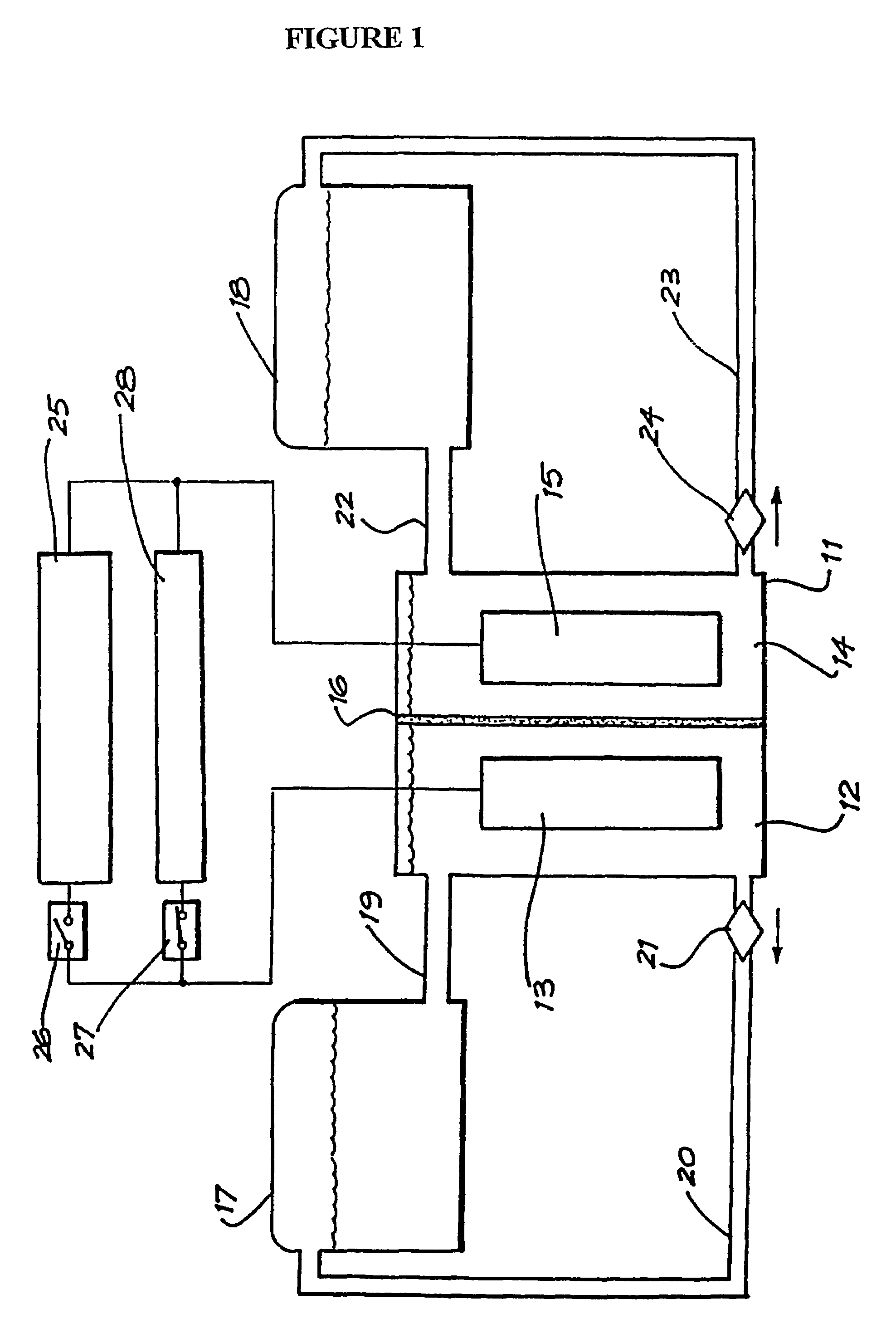
[0066]A redox flow cell according to the present invention was prepared using glassy carbon sheets as the current collectors and graphite felt as the electrode material in both half-cells. A piece of Nafion 112 membrane was used as the ion exchange membrane between the two half-cells and 50 mls of each of the two half-cell electrolytes was placed into the two half-cells. The electrolyte in the negative half-cell was 1.5 M aqueous HCl containing 1 M VCl3, while the electrolyte in the positive half-cell was 1.5 M aqueous HCl containing 1 M NaBr. The solutions were pumped through the cell and a charging current of 20 mA / cm2 applied. When the cell voltage began to increase rapidly, the charging current was switched off and the cell allowed to discharge at a current density of 20 mA / cm2. FIG. 5 shows the plot of cell voltage versus time obtained for the full charge discharge cycle. From this plot, coulombic and voltage efficiency values were calculated as 83% and 80% respectively.


PUM


Abstract

The invention relates to a redox flow cell containing a polyhalide/halide redox couple in the positive half-cell electrolyte and a V(III)/V(II) redox couple in the negative half-cell electrolyte. The invention also relates to a method of producing electricity by discharging the fully charged or partially charged redox flow cell, and a method of charging the discharged or partially discharged redox flow cell.

Description

TECHNICAL FIELD[0001]The present invention relates to novel redox flow cells. In particular, the present invention relates to novel redox flow cells comprising a polyhalide / halide redox couple in the positive half-cell electrolyte and the V(III) / V(II) redox couple in the negative half-cell electrolyte. The invention also relates to a method of producing electricity by discharging a fully charged or partially charged redox flow cell of the present invention, and a method of charging a discharged or partially discharged redox flow cell of the present invention.BACKGROUND[0002]A redox flow cell (also called a redox flow battery) is an electrochemical system which allows energy to be stored in two electrolytes containing different redox couples with electrochemical potential sufficiently separated from each other to provide an electromotive force to drive the oxidation-reduction reactions needed to charge and discharge the cell.[0003]A redox flow cell comprises a positive compartment an...

Claims


Application Information

Patent Timeline
IPC IPC(8): H01M8/20H01M10/36H01M2/00H01M8/04186H01M8/18H01M10/44
CPCB60L11/1879H01M8/04186H01M8/188B60L2240/545Y02T10/705H01M2300/0085Y02E60/528Y02T10/7005B60L50/64Y02E60/50Y02T10/70
Inventor SKYLLAS-KAZACOS, MARIA
Owner WATTJOULE
Why Eureka
Try Eureka