Hydrogen generator

a generator and hydrogen technology, applied in the field of apparatus, can solve the problems of not meeting the advancements in miniaturization achieved with pem fuel cells, complicating the use of small consumer applications, and two-tank designs that are not typically directionally independent, and preventing the build-up of reaction products within the device. , to achieve the effect of promoting hydrogen gas generation and preventing the build-up of reaction products

Inactive Publication Date: 2008-01-29
SILICON VALLEY BANK
View PDF11 Cites 47 Cited by
  • Summary
  • Abstract
  • Description
  • Claims
  • Application Information

AI Technical Summary

Benefits of technology

[0011]The present invention provides a compact, orientation independent and self-regulating hydrogen generating system having no moving parts. In accordance with the present invention, the hydrogen gas generating system includes a housing having a catalyst retaining member that separates a fuel holding chamber from a hydrogen chamber. A catalyst that promotes the generation of hydrogen gas upon contact with the fuel is disposed within at least one pore in the catalyst retaining member. The catalytic process may be the catalytic hydrolysis of a metal borohydride solution or the catalytic dehydrogenation or reformation of an alcohol, such as methanol. Each pore in the catalyst retaining member is in communication with the fuel holding and hydrogen chambers. The fuel is in contact with the exterior surface and its molecules can move to such surface without the use of capillary action. The fuel moves into the pores and contacts the catalyst thereupon generating hydrogen gas. In the disclosed embodiments, the catalyst retaining member can take different forms, including one or more hollow elongated members or plates. In addition, the position of the hydrogen fuel interface within the pore can be varied thus regulating the rate of hydrogen generation.
[0012]Advantageously, the fuel holding chamber can be accessed through one or more inlet ports to add fuel as needed. For those fuels that also result in the formation of a non-gaseous product, e.g., sodium borate from sodium borohydride, one or more outlet ports can serve to discharge this material. These ports can be used to wash the device with water or other suitable solvent between fuel refills, to prevent build-up of reaction product within the device. The present invention is also adaptable for use in applications where continuous hydrogen production is desired. In such case, a reservoir can be connected to the fuel holding chamber of the hydrogen generating system to provide a continuous supply of fresh fuel. By circulating the fresh fuel through this chamber spent fuel is removed as fresh fuel is added. The present invention may also be incorporated permanently into a hydrogen consuming device, e.g., a fuel cell where fuel may be added as needed. Or, the generator can be provided as a separate module which is detachable from the hydrogen consuming device.

Problems solved by technology

The technology to create small-scale systems for hydrogen supply, storage, and delivery has not yet matched the advancements in miniaturization achieved with PEM fuel cells.
The existing hydrogen storage options, which include compressed and liquid hydrogen, hydrided metal alloys, and carbon nanotubes, have characteristics which complicate their use in small consumer applications.
However, such two-tank designs are not typically directionally independent and are not amenable to miniaturization.

Method used


Image

  • Hydrogen generator
  • Hydrogen generator
  • Hydrogen generator

Examples


Embodiment Construction

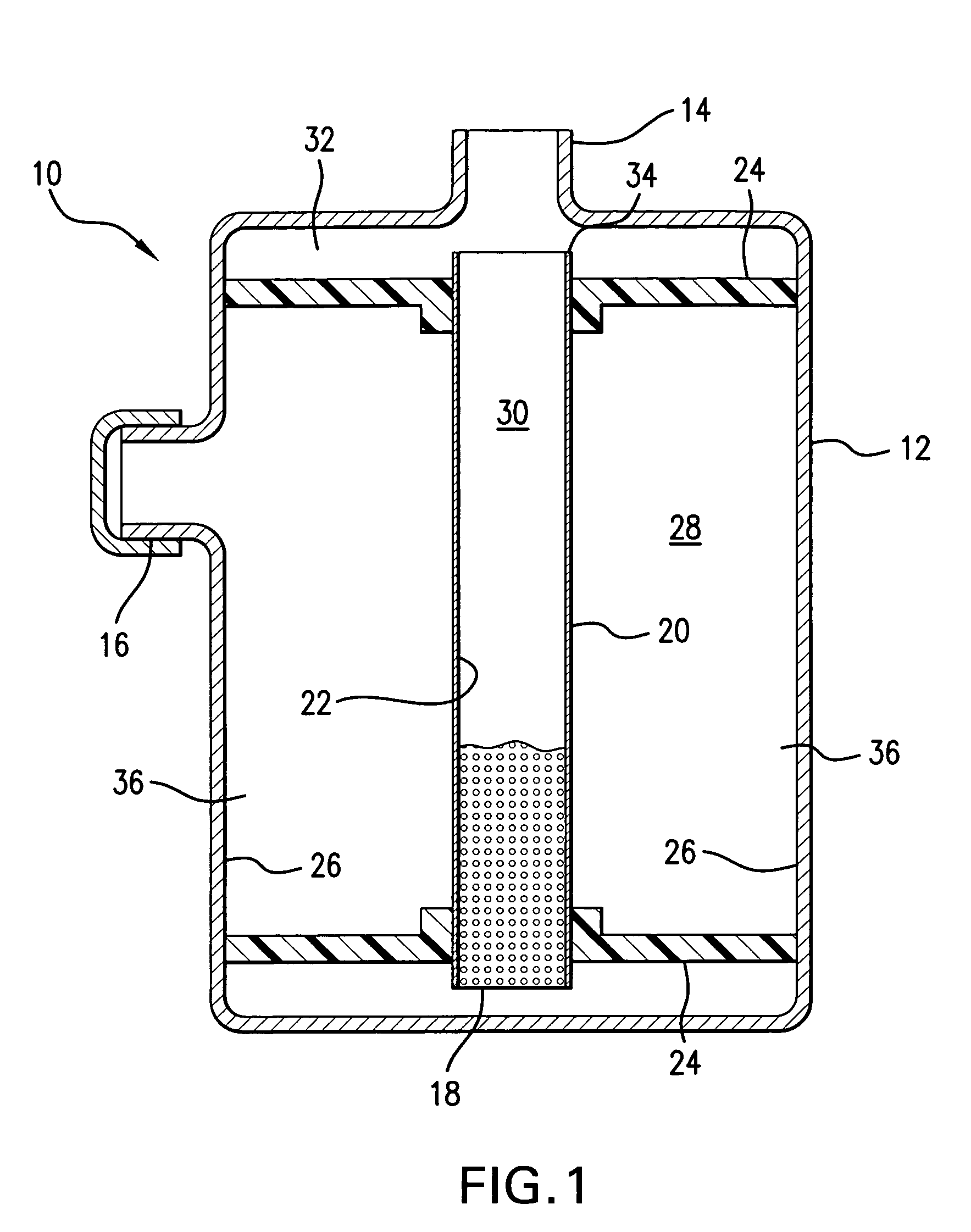
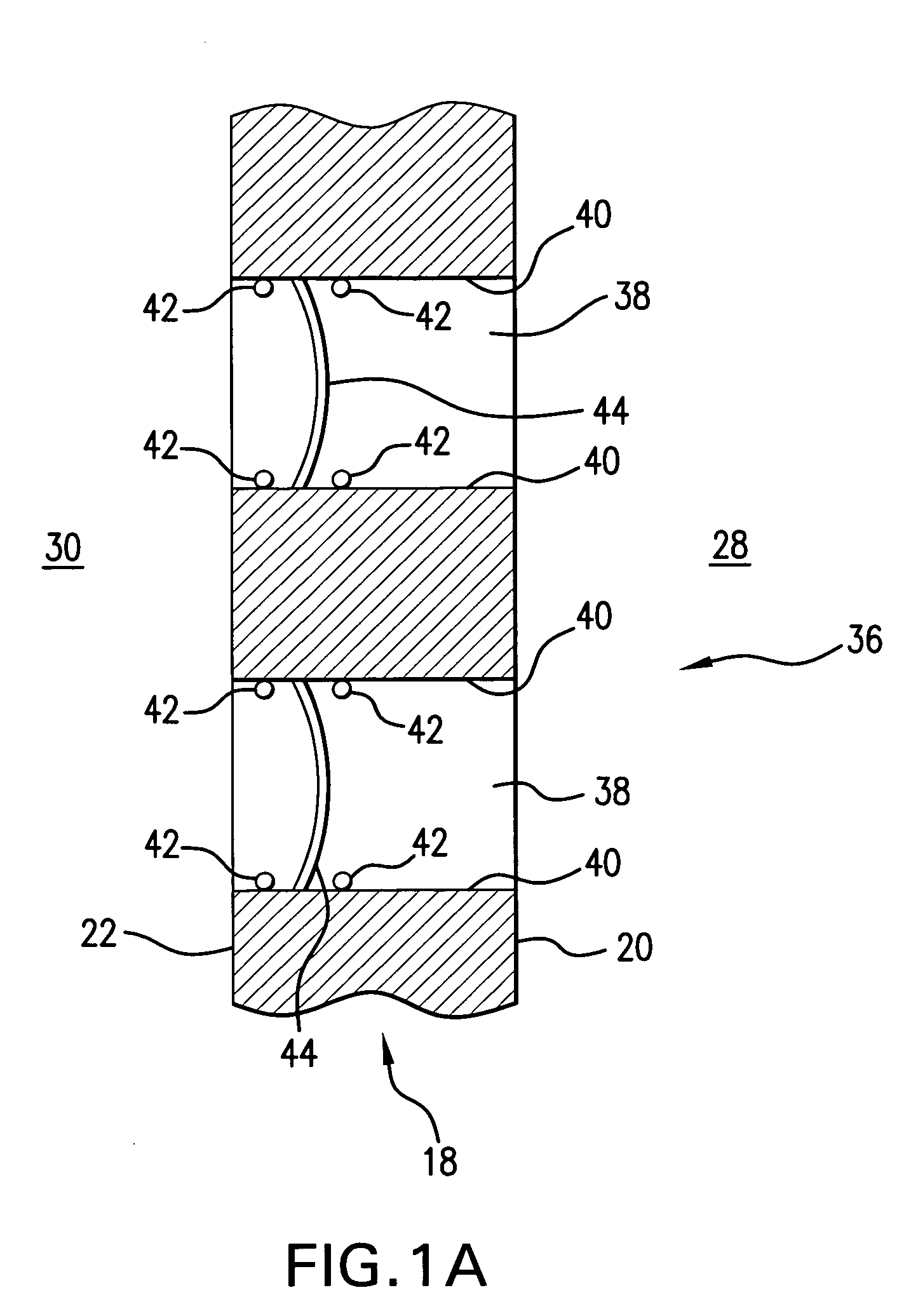
[0023]Refer now to FIG. 1 which shows a cross-sectional view of an illustrative hydrogen gas generation system 10. The hydrogen gas generation system 10 includes a housing 12 having an outlet 14 for removal of the hydrogen gas generated within the housing 12 and a port 16 that can be used to add a fresh fuel solution to the housing 12 or to remove spent fuel solution therefrom as will be later explained below. A catalyst retaining member or reactor member comprising a microporous hollow fiber 18 is positioned within housing 12. Fiber 18 has a first exterior surface 20 and a second exterior surface 22.

[0024]The microporous hollow fiber 18 is held in its position within the housing 12 by seals 24 that are spaced apart along the longitudinal axis of the microporous hollow fiber 18 and the seals 24 may be comprised of epoxy or other sealing material that forms a tight seal against the first exterior surface 20 of the microporous hollow fiber 18 and the interior surface 26 of the housing...


PUM

PropertyMeasurementUnit
contact angleaaaaaaaaaa
hydrophilicaaaaaaaaaa
hydrophobicaaaaaaaaaa

Abstract

A hydrogen generator capable of operating in any orientation and having no moving parts includes a catalyst retaining structure. The catalyst retaining structure is disposed in a housing and serves to separate the housing into a fuel holding portion and a hydrogen chamber. The catalyst retaining structure also includes one or more pores, each pore being in communication with the fuel holding and hydrogen chambers. A catalyst, that promotes the generation of hydrogen gas upon contact with the fuel, is disposed within the pores. The fuel enters the pores and thereupon generates hydrogen gas which passes into the hydrogen chamber. Contact of the fuel with the catalyst in the pores may be controlled and the position of the fuel-hydrogen interface within the pore may be moved so as to regulate the generation of hydrogen. The catalyst retaining structure can take different forms, including one or more hollow elongated members or plates, and may further incorporate hydrophobic and/or hydrophilic membranes.

Description

REFERENCE TO RELATED APPLICATIONS[0001]The present application is based upon and hereby claims priority from Provisional Patent Application 60 / 423,865 filed Nov. 5, 2002 and Provisional Patent Application 60 / 454,297 filed Mar. 13, 2003.TECHNICAL FIELD[0002]The present invention relates to an apparatus which generates hydrogen by exposing a fuel solution to a catalyst and more particularly, to such a generator which uses a porous catalyst retaining structure.BACKGROUND OF THE INVENTION[0003]The development of fuel cells as replacements for batteries in portable electronic devices, including many popular consumer electronics such as personal data assistants, cellular phones, and laptop computers, is dependent on finding a convenient and safe hydrogen source. The technology to create small-scale systems for hydrogen supply, storage, and delivery has not yet matched the advancements in miniaturization achieved with PEM fuel cells.[0004]A hydrogen fuel source for small applications needs...

Claims


Application Information

Patent Timeline
Patent Type & Authority Patents(United States)
IPC IPC(8): B01J8/02B01J7/00C01B3/00B01D63/02B01D69/08B01J19/00B01J19/24C01B3/06C01B3/50
CPCB01D63/02B01D69/08B01J19/0053B01J19/2475B01J19/2485C01B3/065C01B3/501Y02E60/324C01B2203/041C01B2203/0465C01B2203/047C01B2203/066Y02E60/362B01D2313/42Y02E60/36Y02E60/32
Inventor SHAH, SHAILESH A.KELLY, MICHAEL T.
Owner SILICON VALLEY BANK
Why Eureka
Try Eureka