Differential structure programmable gain instrumentation amplifier

a technology of programmable gain and instrumentation amplifier, which is applied in the direction of different amplifiers, amplifiers with semiconductor devices/discharge tubes, dc-amplifiers with dc-coupled stages, etc., can solve the problems of insufficient performance for certain daq systems, insufficient linearity and speed, inaccurate conversion data, etc., to achieve increased output swing, increase signal to noise ratio, and gain switching

Active Publication Date: 2008-02-05
NATIONAL INSTRUMENTS
View PDF17 Cites 6 Cited by
  • Summary
  • Abstract
  • Description
  • Claims
  • Application Information

AI Technical Summary

Benefits of technology

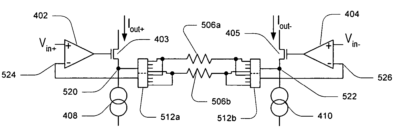
[0017]In one embodiment, an output circuit may be implemented to convert the differential output current produced by the input stage of the PGIA to a differential output voltage. The differential output voltage may be produced by a pair of output op-amps and may provide an increased output swing for higher signal to noise ratio (SNR) and increased symmetry for higher common mode rejection ratio (CMRR). The output circuit may be configured with a composite differential I / V converter design used in establishing the voltage potential at which the currents are sensed. Each input of a low noise op-amp may be coupled to a respective inverting input of a respective one of the pair of output op-amps, with the output of the low noise op-amp coupled to a respective non-inverting input of one of op-amps. In this configuration, the output op-amps may be selected to have a high operating speed without a requirement for them to be highly precise. Benefits of this configuration may include high operating speed and low noise, where both factors may be optimized independently. In some embodiments, bias current may be reduced by coupling a respective FET with a corresponding respective biasing current source to the inverting input of each op-amp, with the drain of the FET coupling to a positive rail voltage, the source of the FET coupling to the inverting input of the op-amp and the gate of the FET serving as the new inverting input for the op-amp.
[0018]In one embodiment, the output common-mode voltage of the output circuit may be set according to a common-mode feedback configuration. In this configuration, the individual components of the differential output voltage may each be responsive to the differential input current as opposed to each individual component of the differential output voltage being responsive to the respective individual component of the differential input current. Additionally, without common-mode feedback, all supply voltages and bias currents may need to be set precisely in order to obtain the correct output common-mode voltage. The common-mode feedback configuration may be implemented with output clamping using a respective diode configured in the respective feedback path of each respective one of the pair of output op-amps. Each diode may keep the respective output voltage of the respective output op-amp from exceeding a voltage level that is the equivalent of the I / V converter's corresponding current-sensing node. Common-mode feedback ensures that when one voltage output (of the differential voltage output) is clamped in the positive direction, the other voltage output is clamped in the negative direction. In one set of embodiments, the diodes may be base-collector junctions of high-speed bipolar junction transistors (BJTs), which may provide a combination of low capacitance, low leakage, and high speed. In alternate embodiments, the diodes may be implemented using other structures and / or designs functionally equivalent to diodes.
[0019]In one embodiment, the precision current conveyors may be designed to prevent op-amp saturation without causing extra current flow and / or to maintain a stable feedback loop during overload conditions. In one set of embodiments, the op-amps used in implementing the precision current conveyors may be bootstrapped by moving the supply rails with the input and output signals, in order to improve the op-amps' large-signal behavior, including slew rate and common-mode rejection.

Problems solved by technology

For example, the PGIA must settle before the A / D conversion takes place or the converted data may be inaccurate.
Traditional PGIAs typically use operational amplifiers (op-amps) with multiplexers to switch feedback networks, which may not always facilitate the required performance, namely linearity and speed, at desired levels.
Typical PGIAs that use current conveyors and are currently available on the market are slowed by global feedback or have other limitations, providing what may be insufficient performance for certain DAQ systems.

Method used


Image

  • Differential structure programmable gain instrumentation amplifier
  • Differential structure programmable gain instrumentation amplifier
  • Differential structure programmable gain instrumentation amplifier

Examples


Embodiment Construction

[0036]As used herein, a “bootstrap” circuit or “bootstrapping” circuit refers to a circuit configured to drive the power rails of a specified circuit or specified sub-circuit with a signal that is substantially similar to the signal the specified circuit is configured to process, in order to make the signal appear small to the circuit. This may allow the specified circuit to operate in a more linear manner and to present a more manageable load to the signal. Furthermore, a “double multiplexer” refers to two multiplexers switching in concert, that is, the two multiplexers are selecting the same corresponding channels at the same time. For example, a signal may be an input to a first channel of a first multiplexer and another signal may be an input to a first channel of a second multiplexer. Then, whenever the first multiplexer is operated to select its respective first channel, the second multiplexer is operated to simultaneously select its own respective first channel. In some embod...


PUM


Abstract

In one embodiment, a programmable gain instrumentation amplifier (PGIA) comprises a pair of current conveyors, each current conveyor having a respective sense node and a respective voltage input, with a gain-setting resistor coupled between the respective sense nodes, and current being sensed on both sides of the gain setting resistor. In one embodiment, each current conveyor comprises a corresponding operational amplifier (op-amp) having a non-inverting input configured as the respective voltage input that may receive a respective input voltage signal, an output and an inverting input, with a respective current conveying element, which may be a FET, configured in a feedback loop between the output and the inverting input. Each current conveyor may be configured to sense a corresponding current flowing through its respective FET, with the corresponding currents forming a differential output current of the PGIA. The respective input voltage signals received by the respective voltage inputs may form a differential input voltage of the PGIA. In one set of embodiments, the PGIA may be implemented with a differential voltage output, leading to an increased output swing for higher signal-to-noise ratio and increased symmetry for a higher common mode rejection ratio.

Description

PRIORITY CLAIM[0001]This application claims benefit of priority of provisional application Ser. No. 60 / 602,216 titled “Differential Structure Programmable Gain Instrumentation Amplifier” and filed Aug. 17, 2004, which is hereby incorporated by reference as though fully and completely set forth herein.BACKGROUND OF THE INVENTION[0002]1. Field of the Invention[0003]This invention relates generally to measurement and data acquisition systems and, more particularly, to instrumentation amplifier design.[0004]2. Description of the Related Art[0005]Scientists and engineers often use measurement systems to perform a variety of functions, including measurement of a physical phenomena or unit under test (UUT), test and analysis of physical phenomena, process monitoring and control, control of mechanical or electrical machinery, data logging, laboratory research, and analytical chemistry, to name a few examples.[0006]A typical measurement system comprises a computer system, which commonly feat...

Claims


Application Information

Patent Timeline
Patent Type & Authority Patents(United States)
IPC IPC(8): H03F3/45
CPCH03F3/45744H03F3/45183H03F3/45197H03F3/45475H03F3/45735H03F2200/261H03F2203/45356H03F2203/45496
Inventor REGIER, CHRISTOPHER G.
Owner NATIONAL INSTRUMENTS
Why Eureka
Try Eureka