Method of manufacturing chemical mechanical polishing pad

a technology of mechanical polishing and manufacturing method, which is applied in the direction of manufacturing tools, flexible wheel parts, grinding devices, etc., can solve the problems of unsatisfactory polishing surface state, greatly affected polishing result, and unsatisfactory polishing rate, so as to achieve excellent polishing rate and suppress the occurrence of scratches.

Active Publication Date: 2008-02-12
JSR CORPORATIOON
View PDF25 Cites 49 Cited by
  • Summary
  • Abstract
  • Description
  • Claims
  • Application Information

AI Technical Summary

Benefits of technology

[0005]It is an object of the present invention which has solved the above problems of the prior art to provide a method of manufacturing a chemical mechanical polishing pad which fully suppresses the occurrence of a scratch on the polished surface and has an excellent polishing rate.

Problems solved by technology

It is known that the polishing result is greatly affected by the performance characteristic and properties of the polishing pad in this chemical mechanical polishing.
Although the design of a chemical mechanical polishing pad is described in detail in the above patent document, JP-A 11-70463, the polishing rate and the state of the polished surface are still unsatisfactory.

Method used


Image

  • Method of manufacturing chemical mechanical polishing pad
  • Method of manufacturing chemical mechanical polishing pad
  • Method of manufacturing chemical mechanical polishing pad

Examples


example 1

(1) Manufacture of Chemical Mechanical Polishing Pad

[0136]80 parts by volume (equivalent to 72 parts by mass) of 1,2-polybutadiene (manufactured by JSR Corporation, trade name of JSR RB830) and 20 parts by volume (equivalent to 28 parts by mass) of β-cyclodextrin (manufactured by Bio Research Corporation of Yokohama, trade name of Dexy Pearl β-100, average particle diameter of 20 μm) as water-soluble particles were kneaded together by an extruder set at 160° C. 1.0 part by volume (equivalent to 0.44 parts by mass of pure dicumyl peroxide) of Percumyl D40 (trade name, manufactured by NOF Corporation, containing 40 mass % of dicumyl peroxide) as dicumyl peroxide was added to and kneaded with the above kneaded product at 120° C. to obtain a pellet of a composition for forming a chemical mechanical polishing pad. This pellet was fed to the inside of a mold and heated at 170° C. for 18 minutes to be crosslinked so as to obtain a disk-like molded product having a diameter of 600 mm and a ...

example 2

[0145]28.2 parts by mass of polytetramethylene glycol having two hydroxyl groups at both terminals of the molecule and a number average molecular weight of 650 (manufactured by Mitsubishi Chemical Co., Ltd., trade name of PTMG650) and 21.7 parts by mass of 4,4′-diphenylmethane diisocyanate (manufactured by Sumika Bayer Urethane Co., Ltd., trade name of Sumidule 44S) were fed to a reactor and maintained at 90° C. for 3 hours under agitation to carry out a reaction, and then cooled to obtain a prepolymer having an isocyanate group at both terminals.

[0146]14.5 parts by mass of β-cyclodextrin (manufactured by Bio Research Corporation of Yokohama, trade name of Dexy Pearl β-100, average particle diameter of 20 μm) as water-soluble particles was dispersed into 21.6 parts by mass of polypropylene glycol having three hydroxyl groups and a number average molecular weight of 330 (manufactured by NOF Corporation, trade name of Uniol TG300, addition reaction product of glycerin and propylene ox...

example 3

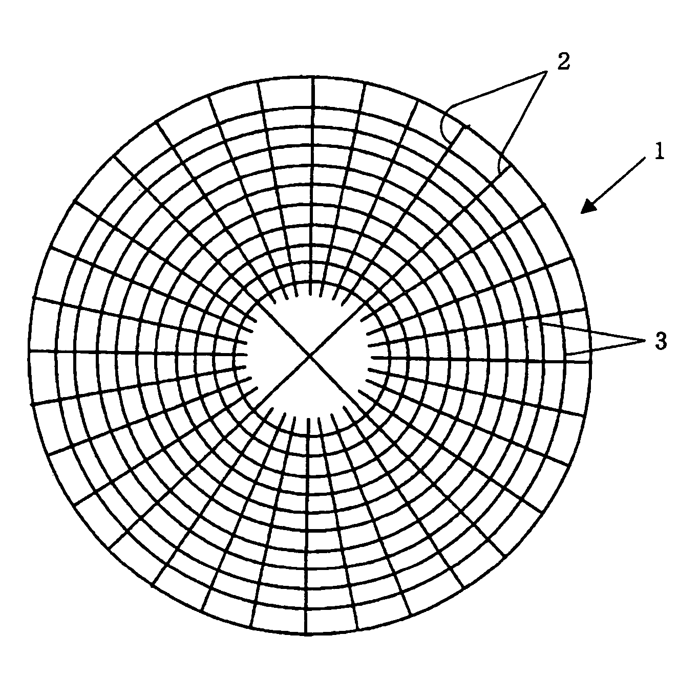
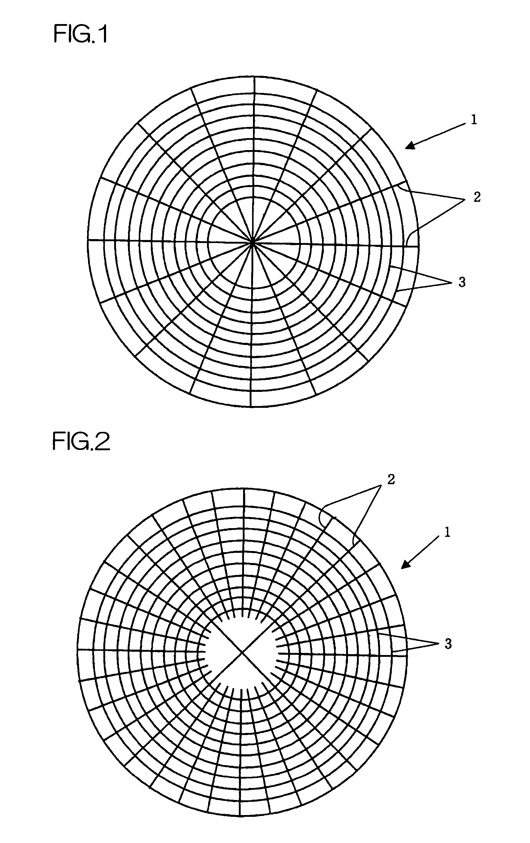
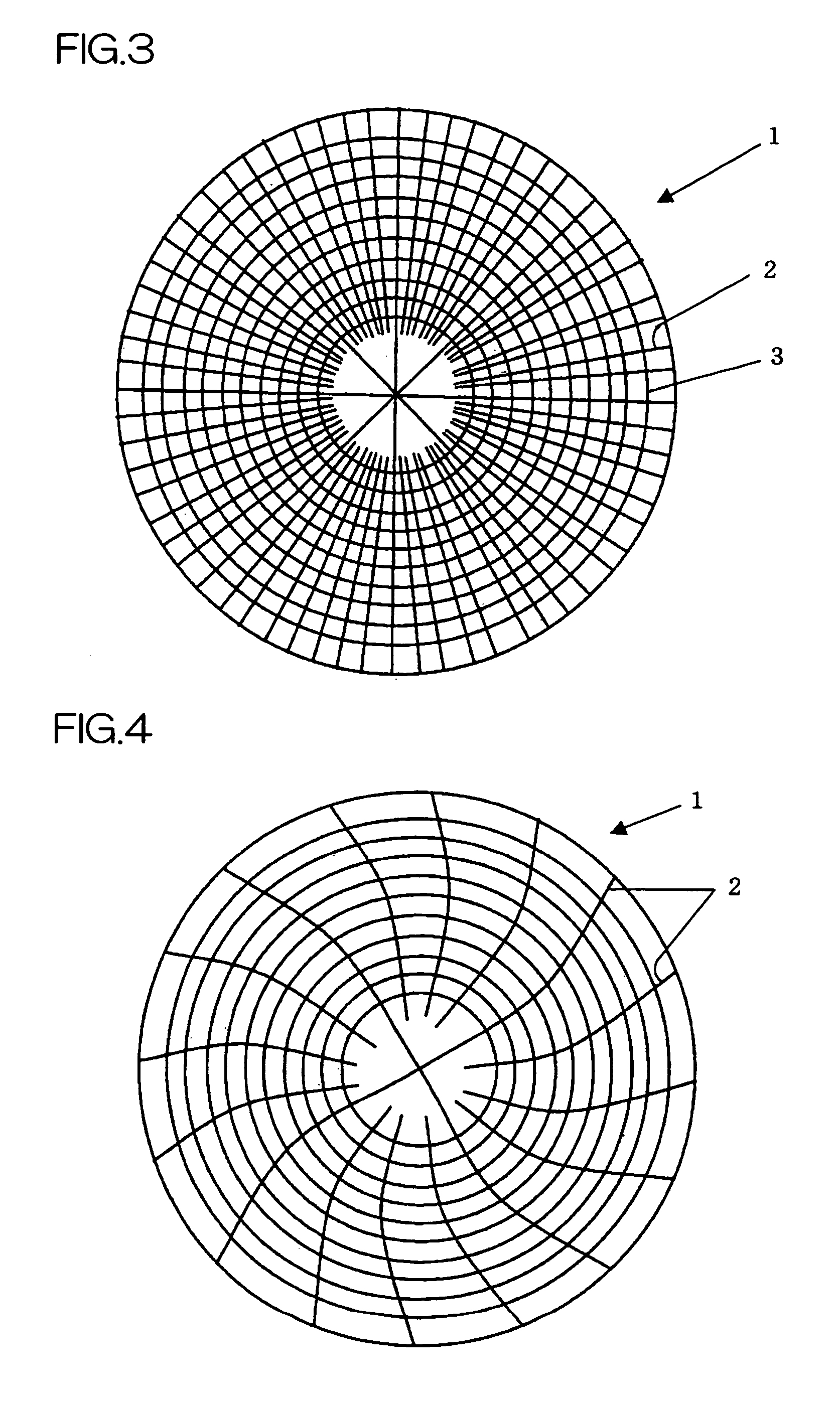
[0151]After the grooves of the first group were formed in the pad-like form in Example 1, four linear grooves (having a width of 1.0 mm and a depth of 1.0 mm) extending from the center to the peripheral end of the pad were formed as grooves of the second group by a cutting machine equipped with a drive unit capable of angle indexing and positioning in such a manner that they were in contact with one another at the center of the polishing surface of the pad and the angle between adjacent linear grooves was 90°. The four grooves correspond to the four grooves of the second group in contact with one another at the center in FIG. 9. One milling cutter was used to form the four grooves. Further, 28 pairs of linear grooves (the pitch between grooves was 2 mm) extending from points 25 mm away from the center of the pad to the peripheral end of the pad were formed by the same cutting machine as above in such a manner that the angle between adjacent linear grooves was 11.25°. The 28 pairs of...


PUM

PropertyMeasurementUnit
radiusaaaaaaaaaa
widthaaaaaaaaaa
widthaaaaaaaaaa

Abstract

The present invention relates to a method of manufacturing a chemical mechanical polishing pad which provides a chemical mechanical polishing pad which fully suppresses the occurrence of a scratch on the polished surface and has an excellent polishing rate.The method comprising either one of a group of steps (A) and a group of steps (B), the group of steps (A) including(A1) the step of preparing a composition for forming a chemical mechanical polishing pad;(A2) the step of molding the composition for forming a chemical mechanical polishing pad into a pad-like form;(A3) the step of mounting the pad-like form on the round table of a cutting machine having at least a milling unit equipped with a milling cutter, a drive unit capable of angle indexing and positioning and a round table journaled by the drive unit;(A4) the step of forming the second group of grooves with the milling cutter; and(A5) the step of forming the first group of grooves, and the group of steps (B) including(B1) the step of preparing a composition for forming a chemical mechanical polishing pad;(B2) the step of molding the composition for forming a chemical mechanical polishing pad into a pad-like form having the second group of grooves by using a metal mold having projections corresponding to the shapes of the second group of grooves; and(B3) the step of forming the first group of grooves.

Description

FIELD OF THE INVENTION[0001]The present invention relates to a method of manufacturing a chemical mechanical polishing pad which can be advantageously used in a chemical mechanical polishing process.DESCRIPTION OF THE PRIOR ART[0002]In the manufacture of a semiconductor device, chemical mechanical polishing (CMP) is attracting much attention as a polishing technique capable of forming an extremely flat surface. Chemical mechanical polishing is a technique for polishing by letting an aqueous dispersion for chemical mechanical polishing, for example, an aqueous dispersion of abrasive grains flow down over the surface of a chemical mechanical polishing pad while the polishing pad and the surface to be polished are brought into slide contact with each other. It is known that the polishing result is greatly affected by the performance characteristic and properties of the polishing pad in this chemical mechanical polishing.[0003]Heretofore, chemical mechanical polishing has been carried o...

Claims


Application Information

Patent Timeline
Patent Type & Authority Patents(United States)
IPC IPC(8): B24D11/00
CPCB24B19/028B24D13/147B24D18/0009
Inventor HOSAKA, YUKIOTANO, HIROYUKINISHIMURA, HIDEKISHIHO, HIROSHI
Owner JSR CORPORATIOON
Why Eureka
Try Eureka