Stent for vessel

a technology for stents and blood vessels, applied in blood vessels, prostheses, dilators, etc., can solve the problems of stents not being able to reliably support the inner surface of blood vessels, stents are difficult to control precisely, and stents are likely to be expanded excessively

Inactive Publication Date: 2008-02-19
IGAKI IRYO SEKKEI
View PDF15 Cites 10 Cited by
  • Summary
  • Abstract
  • Description
  • Claims
  • Application Information

AI Technical Summary

Benefits of technology

[0015]It is an object of the present invention to provide a stent for a vessel, such as blood vessel, which is able to keep the vessel in the expanded state reliably without injuring the vessel.
[0016]It is another object of the present invention to provide a stent for a vessel which disappears after lapse of a pre-set period after implantation in the vessel to eliminate the necessity of executing a surgical operation of taking out the stent from the vessel after restoration of the site of lesion.
[0018]It is yet another object of the present invention to provide a stent for a vessel which can be inserted into a meandering vessel, such as blood vessel, with good trackability, and which can be easily and reliably implanted in the targeted site in the vessel.
[0026]If a radiopaque medium is mixed into or deposited on the yarn, the state of implantation of the stent in the vessel can be easily checked from outside the living body using X-rays.
[0028]Moreover, if a radiation source radiating β-rays or a radiation source radiating γ-rays is mixed into or deposited on the yarn formed of the biodegradable polymer, these rays can be radiated to the lesion as the stent is inserted into the living body, thus assuring sustained irradiation of radiation rays.

Problems solved by technology

On the other hand, if the balloon expanding stent is deformed after being expanded in diameter and implanted in this condition in the blood vessel, it cannot be restored to its original expanded state, such that there is the risk that the stent cannot support the inner surface of the blood vessel reliably.
With the self-expanding stent formed from a metal linear member, the outer diameter prevailing at the time of expansion is difficult to control precisely, such that the stent is likely to be expanded excessively in comparison with the inner diameter of the blood vessel in which it is implanted.
If the stent inserted into the blood vessel is expanded abruptly, the inner wall of the blood vessel is likely to be injured.
Since the shape memory alloy has extremely high tenacity, such that it exerts an extremely large mechanical pressure to a portion of the inner wall of the blood vessel, thus possibly damaging the blood vessel.
Moreover, there are occasions wherein the stent formed of a shape memory alloy is not uniformly expanded in diameter against the inner wall of the blood vessel when implanted in the blood vessel.
If a portion of the stent compresses against the inner wall of the blood vessel prematurely to commence to be expanded in diameter, the blood vessel cannot be expanded uniformly.
In this case, the portion of the blood vessel, against which a portion of the stent has compressed prematurely, is enlarged excessively in diameter, and hence is likely to be damaged.

Method used


Image

  • Stent for vessel
  • Stent for vessel
  • Stent for vessel

Examples


Embodiment Construction

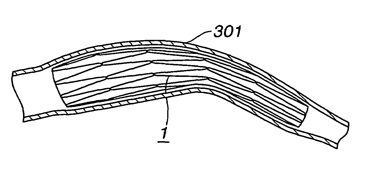
[0042]Referring to the drawings, a stent 1 for the vessel according to the present invention is explained in detail.

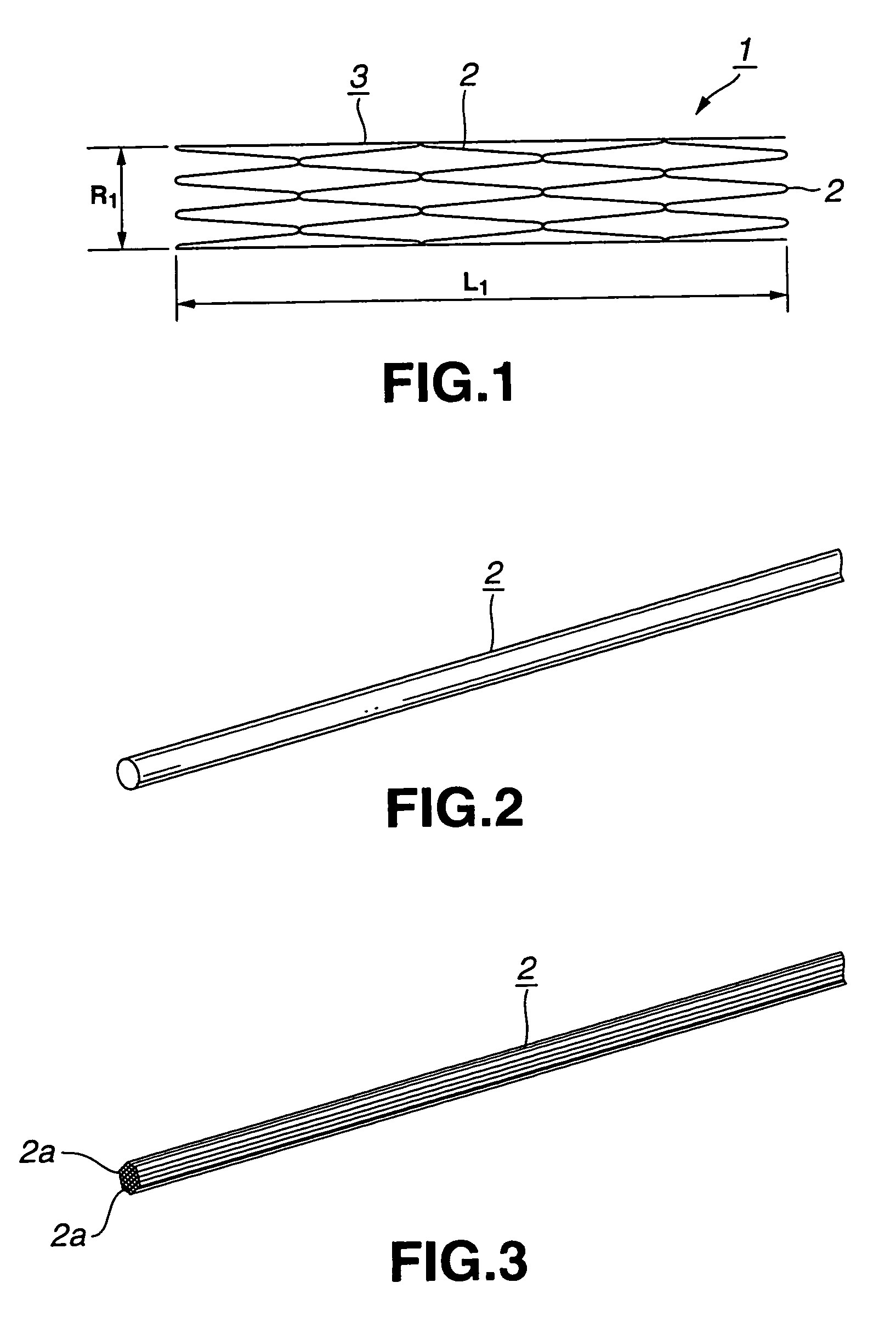
[0043]The stent 1 for the vessel according to the present invention is used as it is inserted into the blood vessel such as coronary artery of a living body and includes a tubular main body portion 3 of the stent comprised of a yarn 2 of a biodegradable polymer having the shape memory function, as shown in FIG. 1.

[0044]The yarn 2 is formed of a biodegradable polymer which does not affect the living body when the yarn is implanted in a living body, such as a human body. As this biodegradable polymer, polylactic acid (PLLA), polyglicolic acid (PGA), polyglactin (copolymer of polyglycolic acid and polylactic acid), polydioxanone, polygliconate (copolymer of trimethylene carbonate and glicolid), or a copolymer of polyglicolic acid or polylactic acid and ε-csaprolactone. It is also possible to use a biodegradable polymer obtained on compounding two or more of these material...


PUM

PropertyMeasurementUnit
glass transition temperatureaaaaaaaaaa
length L1aaaaaaaaaa
length L1aaaaaaaaaa

Abstract

A stent for a vessel implanted in the vessel of the living body including a main body portion of the stent formed into a tube by a yarn formed of a biodegradable polymer exhibiting a shape memory function. The main body portion of the stent is shape-memorized to a size that can be inplanted in the vessel. The main body portion of the stent is implanted in the vessel of the living body as it is contracted in diameter by an external force, and is enlarged in diameter by being heated with the temperature of the living body. The main body portion of the stent is formed by winding a yarn formed of a biodegradable polymer in a tube form as the yarn is bent in a zigzag design. The main body portion of the stent is enlarged or contracted in diameter with the bends of the yarn as the displacing portions.

Description

[0001]This application is a continuation of U.S. application Ser. No. 09 / 530,986 filed Jun. 9, 2000 now U.S. Pat. No. 6,500,204, which was the National Stage of International Application No. PCT / JP99 / 04884, filed Sep. 8, 1999.TECHNICAL FIELD[0002]This invention relates to a stent for the vessel mounted in the vessel, such as blood vessel, lymphatic vessel, bile duct or urinary duct to maintain a constant state in the lumen of the vessel.BACKGROUND ART[0003]Heretofore, if a stenosis portion has occurred in the vessel of a living body, in particular the blood vessel, such as artery, a balloon forming portion provided in the vicinity of the distal end of the balloon catheter is inserted into this stenosis portion. This balloon forming portion is expanded to form a balloon to expand the stenosis portion of the blood vessel to improve the blood flow, by way of the transcutaneous blood vessel forming technique (PTA).[0004]It has been clarified that, if the PTA is applied, stenosis tends t...

Claims


Application Information

Patent Timeline
Patent Type & Authority Patents(United States)
IPC IPC(8): A61F2/06A61M29/00A61F2/00A61F2/02A61F2/915A61L31/14A61M29/02
CPCA61F2/90A61L31/14A61L31/148D01F6/625D01F6/84A61F2/88A61F2210/0004A61F2210/0014A61F2230/0054A61F2002/91575A61L2400/16A61M29/00
Inventor IGAKI, KEIJI
Owner IGAKI IRYO SEKKEI
Why Eureka
Try Eureka