Back-scattered X-ray radiation attenuation method and apparatus
a backscattered x-ray and radiation attenuation technology, applied in the field of x-ray radiography, can solve the problems of noise, noise, and inability to provide useful signals, and achieve the effect of reducing the number of x-ray photons in the backscattered x-ray radiation attenuation field, and reducing the number of x-ray photons in the backscattered field
- Summary
- Abstract
- Description
- Claims
- Application Information
AI Technical Summary
Benefits of technology
Problems solved by technology
Method used
Image
Examples
embodiment 60
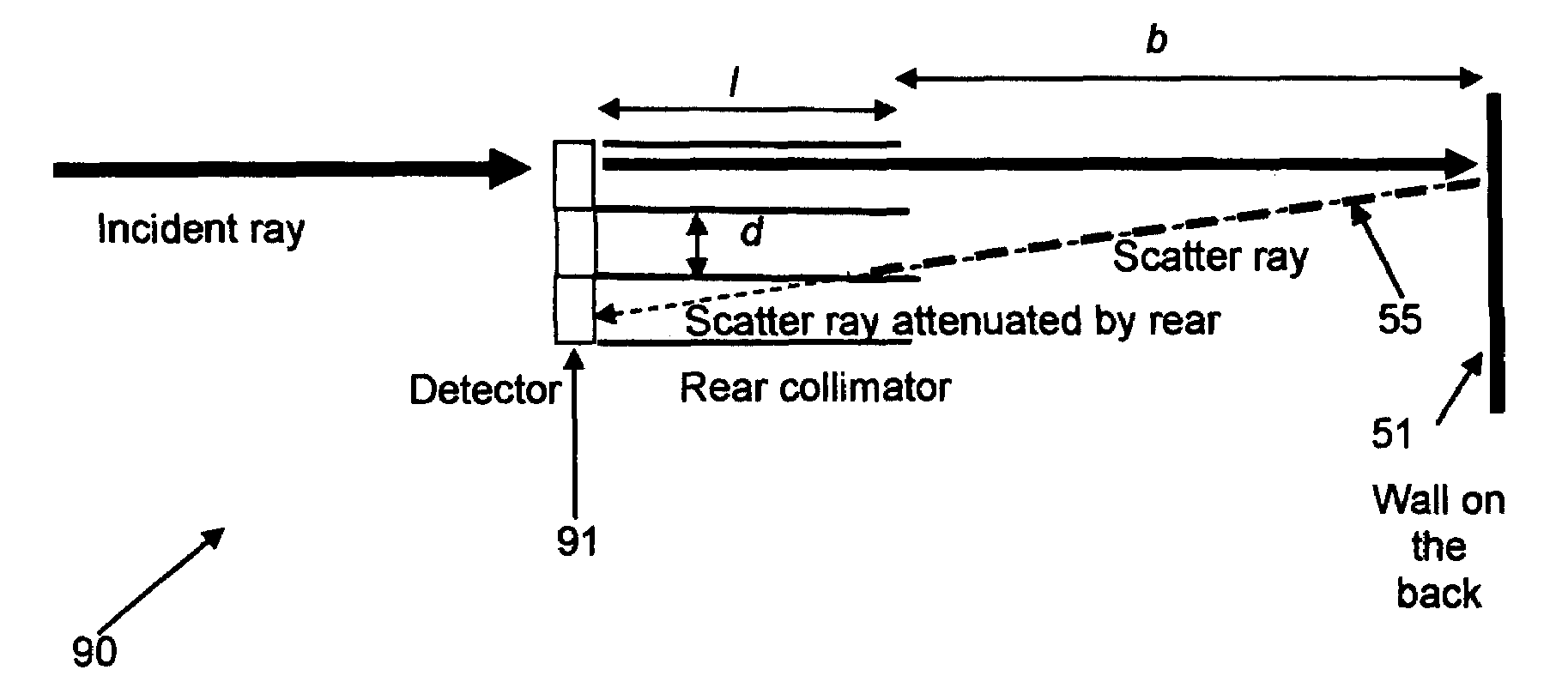
[0061]As shown in FIG. 5, an embodiment 60 of a back-scatter attenuator apparatus according to the present invention includes a pair of parallel, upper and lower baffle plates or collimator plates 64, 65, respectively, which protrude from a rear surface 63 of a detector element 61 of a detector array 62. As will be explained in further detail below, baffle plates 64, may have a length I rearward from the detector of different values depend on desired performance parameters. Also, baffle plates 64, 65 may have different widths w (perpendicular to the page in FIG. 5, as indicated in FIG. 6), but preferably have a width at least as great as that of detector element 62.
[0062]Upper and lower baffle plates 64, 65 cooperate to comprise a single-axis rear collimator 66. The baffle plates 64, 65 are preferably made of a material which has significantly high absorption characteristics for X-ray radiation having energies in the range emitted by X-ray radiation source 40. Therefore, collimator ...
embodiment 70
[0067]As shown in FIG. 6, in an embodiment 70 of a back-scatter attenuation apparatus according to the present invention, for use with a detector array 71, which has a vertical column of individual detector elements 72, a vertical stack of parallel horizontally disposed collimator baffle plates 74 is disposed rearward from the array, at a distance b behind rear face 73 of the detectors. In a preferred configuration of this embodiment, the upper and lower edges of each detector element 71 are horizontally aligned with separate upper and lower collimator baffle plates 74; thus, for a columnar array 71 of N detectors, N+1 collimator baffle plates 74 are provided. The N+1 collimator baffle plates 74 together form an N-channel, single-axis rear collimator 76. The front edges 77 of collimator baffle plates 74 are preferably located a distance b rearward from rear surfaces 73 of detector elements to allow service access to detector array 71.
[0068]FIG. 7 illustrates a “two-axis” embodiment ...
embodiment 150
[0077]FIG. 13 illustrates another variation 150 of a back-scatter attenuating rear collimator for attenuating back-scattered X-ray radiation according to the present invention. Embodiment 150 is desirably used with detector arrays in which the spacing between individual detectors elements is relatively large. Such detector arrays enable X-ray radiation to pass unattenuated through gaps between adjacent detectors to impinge on a back-stop wall and produce thereat back-scattered radiation of relatively high intensity. In this situation, it is desirable to position rear collimator baffle plates according to the present invention in longitudinal, axial alignment with detector elements. Otherwise, unattenuated high intensity X-ray radiation would impinge on the forward edges of collimator baffle plates, which would thus become sources of relatively high intensity back-scattered X-ray radiation. Thus, as shown in FIG. 13, for a detector array 151 comprised of detector elements 152 spaced ...
PUM
 Abstract
Description
Claims
Application Information
 - R&D
- Intellectual Property
- Life Sciences
- Materials
- Tech Scout
- Unparalleled Data Quality
- Higher Quality Content
- 60% Fewer Hallucinations
Browse by: Latest US Patents, China's latest patents, Technical Efficacy Thesaurus, Application Domain, Technology Topic, Popular Technical Reports.
© 2025 PatSnap. All rights reserved.Legal|Privacy policy|Modern Slavery Act Transparency Statement|Sitemap|About US| Contact US: help@patsnap.com


