
Stamping device

a technology of stamping device and stamping plate, which is applied in the field of stamping plate, can solve the problems of halting the production process, high operating cost, and taking several hours or even an entire day to replace the code numerals, and achieves the effect of simple and cost-effectiv

Active Publication Date: 2008-03-04
HANSEN BERND
View PDF18 Cites 1 Cited by
  • Summary
  • Abstract
  • Description
  • Claims
  • Application Information

AI Technical Summary

Benefits of technology

[0007]Objects of the present invention are to provide improved molding processes and devices where an exchange process of the identification data for plastic containers may be carried out in a simple and cost-effective manner, and especially so that the production process itself for plastic containers is not impaired as a result.
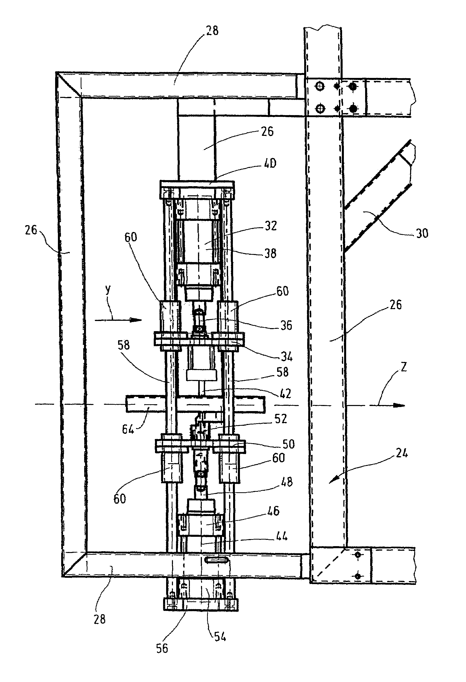
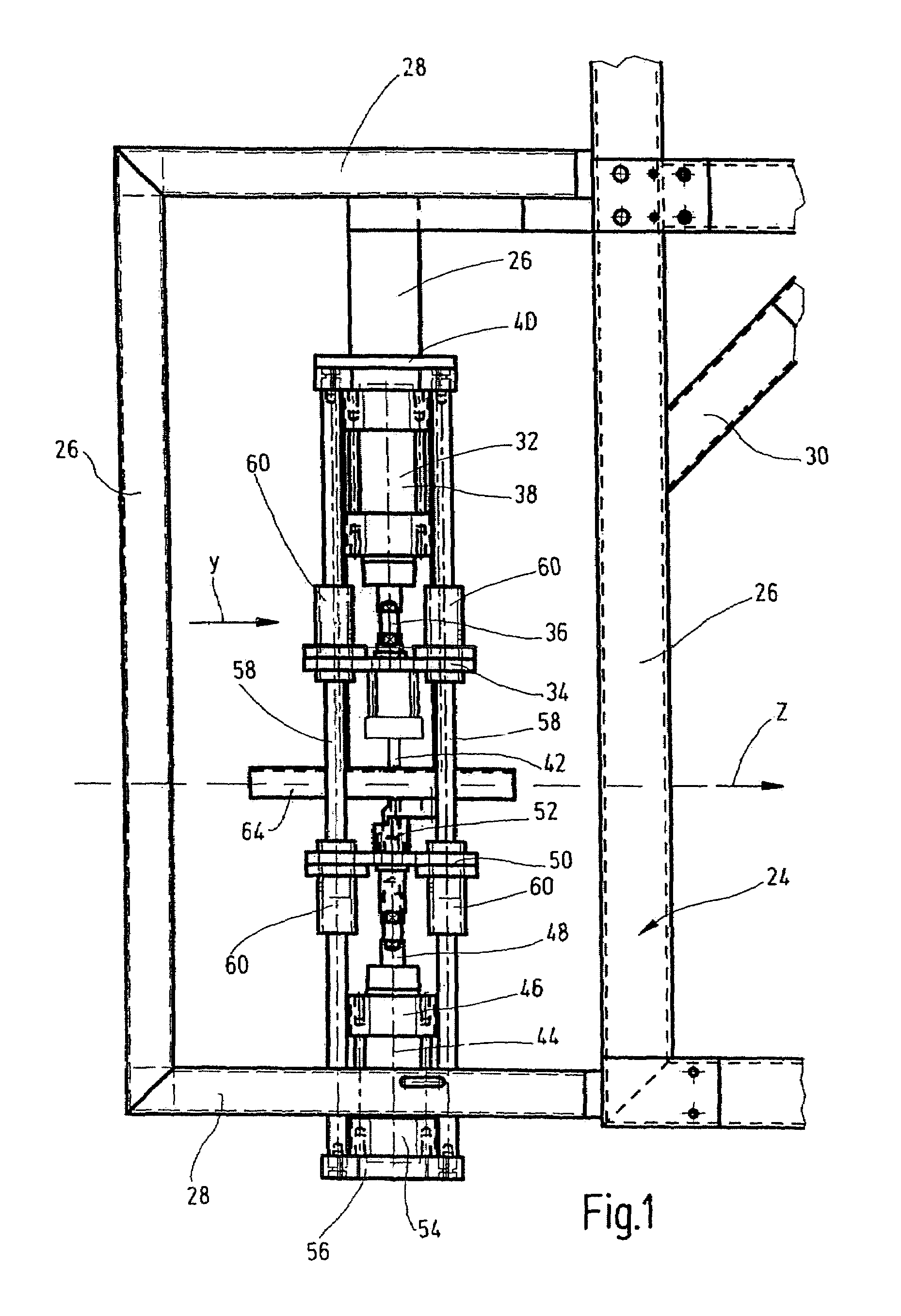
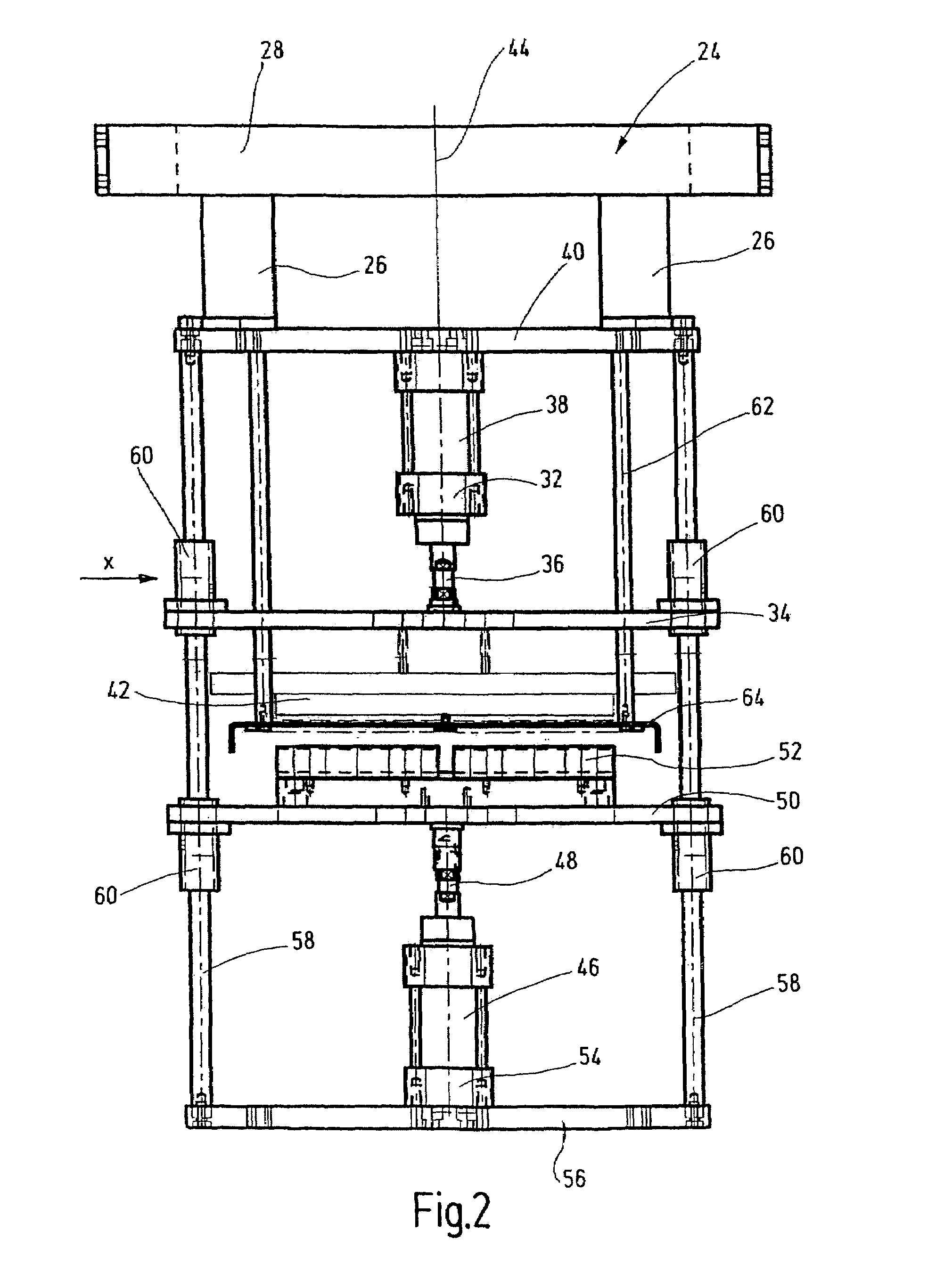
[0009]The stamping device is mounted outside the production machine proper for execution of the blow-fill-seal process. The containers are first fully produced, filled, and sealed before they are moved further to the stamping device for stamping of identification data. The stamping device of the present invention, with its frame structure and the stamp, permits very high rates of output of goods to be stamped. As a rule, the stamping process may basically be disconnected from the production process proper in time and space by the stamping device. In addition, because of its frame structure the stamping device is very easily accessible from the exterior, and a process of exchange of identification data for the containers (ampules) in rapid succession and with little adjustment effort may be achieved. The latter is a factor in particular if, as a result of incorrect selection of code numerals, the stamping processes must be interrupted and the incorrect code numerals, replaced with the correct ones. From the viewpoint of safety engineering the stamping device is easy to control. When supplemented by safety engineering system elements, it may help prevent hazardous conditions for operating personnel.
[0011]It has been found to be especially advantageous to deliver and remove the plastic product in the direction transverse to that of stamping with the stamp and to employ a stamp support supporting the plastic product. The stamp support is moved simultaneously with the stamp or desynchronized from it in the opposite direction of movement. This configuration makes it possible to operate the production machine at high speeds of output of plastic products safely and at the same speed of production as that of the machine.
[0012]In another preferred embodiment of the stamping device of the present invention, the frame has columnar guides for longitudinal movement of the plate-like stamping unit and a support plate for the stamp. The frame structure of the stamping device is reinforced by the columnar guides, so that high accuracy may be achieved in stamping processes, along with clearly recognizable identification data. In addition, the stamping forces generated by the stamping process are reliably transmitted to the frame of the stamping device by the columnar guides. Preferably, the plate-like stamping unit and the support plate are adjacent to and face each other and the piston rods of the stamping plate and the support plate engage the associated plate. Their housing element is rigidly connected to the frame. In this way, the base structure of the frame with the columnar guides may be additionally rigidified by the housing element stamp configured as an operating cylinder. Hydraulic or pneumatic cylinders, as well as electric motor operators with spindle drives, may be employed as operating cylinders for the stamp and stamp support.
[0014]To allow the greatest possible number of stamping processes to be carried out with the plastic products, in one preferred embodiment of the stamping device of the present invention, the plastic products in the form of ampules are configured as containers connected to each other in a strip by a (waste) edge zone, and are stamped in succession with several adjacent ampules being provided simultaneously with the stamp.

Problems solved by technology

Since the production machines involved may easily have ten or more single-use molds, it may take several hours or even an entire day to replace the code numerals in the form of die plates or individual type which are to be fitted into the mold.
Since application of the code numerals inside the molds by hand is a very complicated process, it is also possible that a single error, such as application of an incorrect code numeral in the mold, may make it necessary to halt the production process and dispose all the containers produced up to that point by the production machine in the process.
In such exchange processes the machine for producing the containers is not available, resulting in high operating costs.

Method used


Image

  • Stamping device
  • Stamping device
  • Stamping device

Examples


Embodiment Construction

[0020]The plastic product shown in FIG. 3 has three containers 10 interconnected in sequence in a strip by an edge zone 12, also of plastic. The interior 14 of the container 10 is filled with a fluid such as one in the form of a pharmaceutical preparation or the like. A neck element 16 is sealed by a toggle seal or a toggle seal element 20. A separation point 18 facilitates the opening of the container. The edge waste zone of flat plastic material possibly still present between edge zone 12 with neck element and the toggle seals 20 as shown in FIG. 3 is removed, preferably by punching. The toggle seal 20 is configured to be flat and permits easy opening of the container 10 by manual separation (rotation) of the toggle seal by the separation point 18 from the associated neck element 16.

[0021]Such containers 10 are produced by the above disclosed processes and molding devices (not shown), ones in which a tube of plasticized material is extruded into a molding device. One end of the tu...


PUM

PropertyMeasurementUnit
movementaaaaaaaaaa
pressureaaaaaaaaaa
areaaaaaaaaaaa

Abstract

A stamping device stamps characteristic data, especially in the form of code numbers (22), into plastic products. Such containers are preferably produced according to blowing, filling and gelling methods. At least one stamp (32), having a stamping unit (34) with interchangeable characteristic data units (42), is guided in the longitudinal direction in the frame (24) of the device. When the stamp is in an elevated position, the products to be stamped and / or have been stamped can be fed or removed. When in a lowered position, the products are stamped.

Description

FIELD OF THE INVENTION[0001]The present invention relates to a stamping device for stamping identification data, especially in the form of code numerals, in plastic products such as containers which have been produced preferably by a blow-fill-seal process.BACKGROUND OF THE INVENTION[0002]Processes and molding devices for production of containers have been disclosed in the prior art (DE 199 26 329 A1). A tube of plasticized plastic material is extruded into a molding device. One end of the tube is closed by welding. A pneumatic pressure gradient acting on the hose is generated to expand the hose and is applied for the purpose of forming the container on a shaping wall of the molding device consisting of two form tools positioned opposite each other. A suitable filling mandrel is then used to fill the plastic container under sterile conditions. After the filling mandrel has been removed, the container is hermetically sealed with a definable head geometry being formed. Two container s...

Claims


Application Information

Patent Timeline
Patent Type & Authority Patents(United States)
IPC IPC(8): B29C35/08B29C59/02B44B5/00B44B5/02
CPCB44B5/028B44B5/0019B29C59/02B44B5/00B44B5/02
Inventor HANSEN, BERND
Owner HANSEN BERND
Learn More