Noise attenuation apparatus for borehole telemetry

a technology borehole telemetry, which is applied in the field of noise attenuation apparatus for borehole telemetry, can solve the problems of noise source, potential noise source, obscuring signal, etc., and achieve optimal noise attenuation and effective shielding of the telemetry signal band

Inactive Publication Date: 2008-03-18
SCHLUMBERGER TECH CORP
View PDF15 Cites 22 Cited by
  • Summary
  • Abstract
  • Description
  • Claims
  • Application Information

AI Technical Summary

Benefits of technology

[0017]The resonator has a resonance frequency that provide a band stop filter within a frequency band of 1 to 100, preferably 1 to 50, more preferably 5 to 30 and even more preferably 5 to 25 Hz to effectively shield the telemetry signal band from noise that is generated by the pump station.
[0018]According to another aspect of the invention, a complex acoustic filter is formed by combining a system of one or more constrictions in the mud flow system and one or more of the tuned Helmholtz resonators. The Helmholtz resonator is preferably realized as a housing with a chamber or container and a neck tube providing a flow connection between the chamber and the mud flow. By combining constrictions and resonators into a complex acoustic filter, the frequency filtering effect of the system can be suitably shaped to provide an optimal attenuation of noise using, for example, the multiple tunable resonance frequencies of such a system.

Problems solved by technology

Common to MWD techniques is the problem of transmitting data from the bottom of a borehole to a point on the surface where it can be collected and processed.
A major problem with decoding and analyzing the signal is that noise seen by the transducer, generated by the drilling operation, obscures the signal.
There are a number of potential sources of noise generated during MWD.
Another source of noise is a reflected signal that is created when the original signal hits a pulsation dampener, or “desurger”, near the top of the mud column and is reflected back down the hole.
In addition to noise, the MWD / LWD signal may be degraded by the type of mud, the mud pressure, the length and changes in diameter of the drill pipe and its joints, and the pulsation dampener.
Of these potential and actual sources of noise, the noise generated by the mud pumps is often considered to be the one that interferes most dominantly with the signal.
If data transmission rates are increased, clock tracking and timing recovery, and the S / N ratio between the pulser and transducer become very sensitive and difficult to maintain due to the nature of the drilling operations, thus, decreasing the reliability of the MWD data.
As furthermore the gas charge of the desurger is set without knowledge of the telemetry signal, it does not contribute efficiently towards reducing the noise in the telemetry signal band.
However, very large physical size is required to achieve sufficient dampening.

Method used


Image

  • Noise attenuation apparatus for borehole telemetry
  • Noise attenuation apparatus for borehole telemetry
  • Noise attenuation apparatus for borehole telemetry

Examples


Embodiment Construction

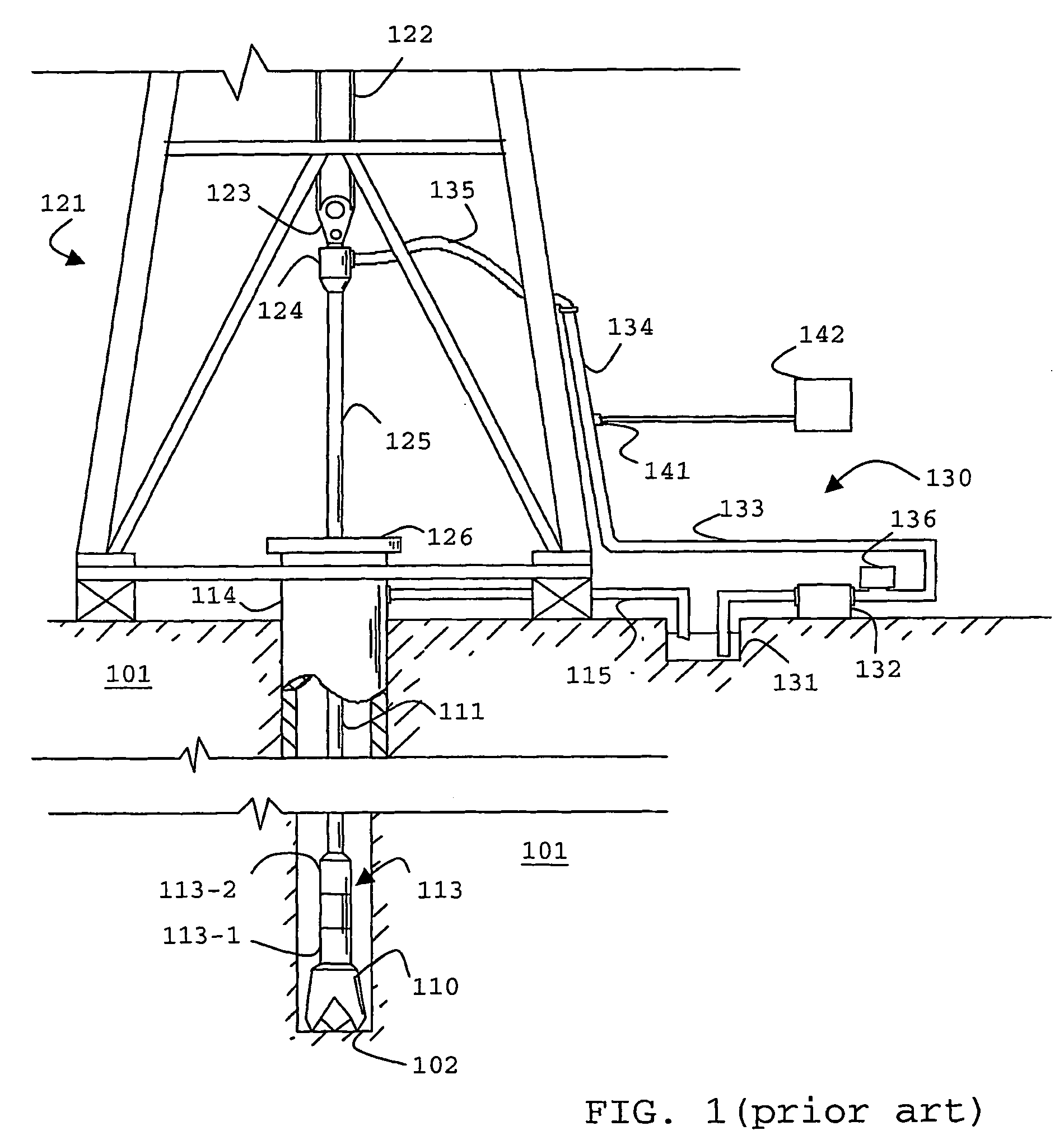
[0034]In FIG. 1, there is shown a known well drilling system configured for MWD operation and having a mud pulse telemetry system. Drill string 111 is shown within borehole 102. Borehole 102 is located in the earth 101. Borehole 102 is being cut by the action of drill bit 110. Drill bit 110 is disposed at the far end of bottom hole assembly (BHA) 113 that is attached to and forms the lower portion of drill string 111. Bottom hole assembly 113 contains a number of devices including

[0035]Measurement-while-drilling (MWD) subassemblies 113-1 for MWD measurements. Examples of typical MWD measurements include direction, inclination, survey data, downhole pressure (inside and outside drill pipe), resistivity, density, and porosity. The signals from the MWD subassemblies are transmitted to mud siren or pulser assembly 113-2. Mud siren assembly 113-2 converts the signals from subassemblies 113-1 into pressure pulses in the drilling fluid. The pressure pulses are generated in a particular pat...


PUM


Abstract

A surface mud pipeline system is described with a mechanical acoustic filter (1245) tuned to a predetermined frequency band so as to attenuate pump noise (132) within this band. The filter can be combined with a Venturi constriction to provide enhanced attenuation and is used to improve signal transmission of a mud pulse telemetry system (113-2).

Description

[0001]The present invention generally relates to an apparatus for attenuating pressure variations within a predetermined frequency band in the surface section of a drilling fluid flow system. It pertains to such apparatus for improving the transmission of telemetry signal between a downhole location and the surface. More specifically, it relates to an apparatus for reducing the pump noise in a mud pulse telemetry system.BACKGROUND OF THE INVENTION[0002]Typical drilling operations employ a number of techniques to gather information such as the depth and inclination of a borehole and the types of rocks through which a drill pipe and drill bit are drilling. For this purpose, techniques called Measurement-While-Drilling (MWD) and Logging-While-Drilling (LWD) were developed in the oil exploration and production industry. These techniques enable the collection of data in real-time. LWD collects logging information similar to the conventional wireline logging, while MWD also enables a dril...

Claims


Application Information

Patent Timeline
Patent Type & Authority Patents(United States)
IPC IPC(8): G01V3/00E21B47/18G01V11/00
CPCE21B47/18G01V11/002
Inventor HUANG, SONGMINGMONMONT, FRANCKFROELICH, BENOIT
Owner SCHLUMBERGER TECH CORP
Why Eureka
Try Eureka