Telescope mirror for high bandwidth free space optical data transmission

a manufacturing process and optical data transmission technology, applied in the direction of optical elements, mountings, instruments, etc., can solve the problems of high cost of precision manufacturing, and achieve the effects of high precision manufacturing, moderate cost, and high bandwidth free space optical communication

Inactive Publication Date: 2008-03-25
MEDIA LARIO SRL
View PDF14 Cites 15 Cited by
  • Summary
  • Abstract
  • Description
  • Claims
  • Application Information

AI Technical Summary

Benefits of technology

[0006]It is therefore an object of the present invention to provide an optical element suitable for high bandwidth free space optical communication which can be manufactured with high precision at moderate costs.
[0008]The method according to the invention provides a telescope mirror having a highly accurate geometry for achieving a high optical performance. The design geometry is realized with high accuracy with the mandrel or masterpiece by machining and polishing techniques known from optical lenses. The mandrel is preferably made of glass or zerodur material. According to the invention the geometry of the mandrel can be replicated many times and with high accuracy through the electroforming process. This high precision can be achieved by controlling the electroforming process such that the building up of internal mechanical tension within the mirror body or shell is suppressed. Consequently the deformation of the mirror geometry through the release of internal mechanical stresses can be avoided.

Problems solved by technology

These are, however, expensive to manufacture with the required precision.

Method used


Image

  • Telescope mirror for high bandwidth free space optical data transmission
  • Telescope mirror for high bandwidth free space optical data transmission
  • Telescope mirror for high bandwidth free space optical data transmission

Examples


Embodiment Construction

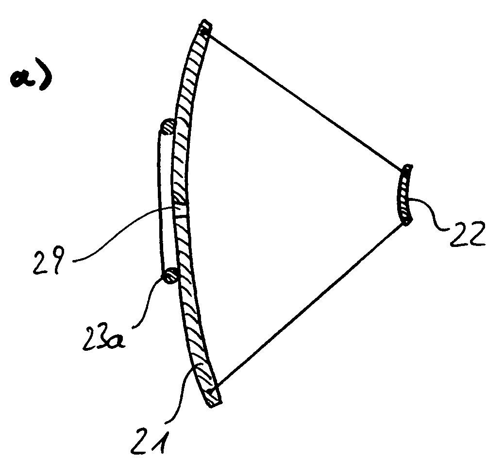
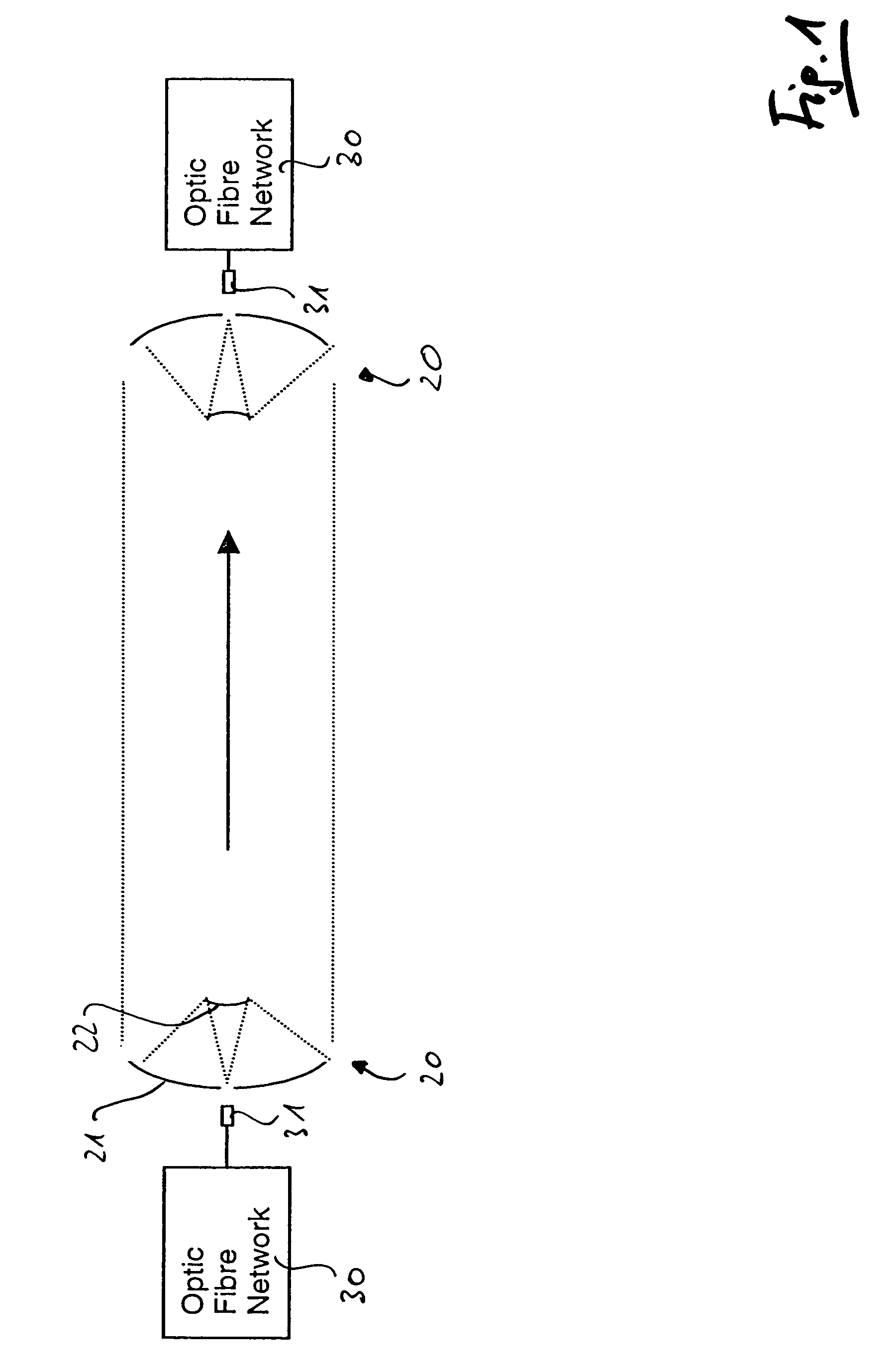
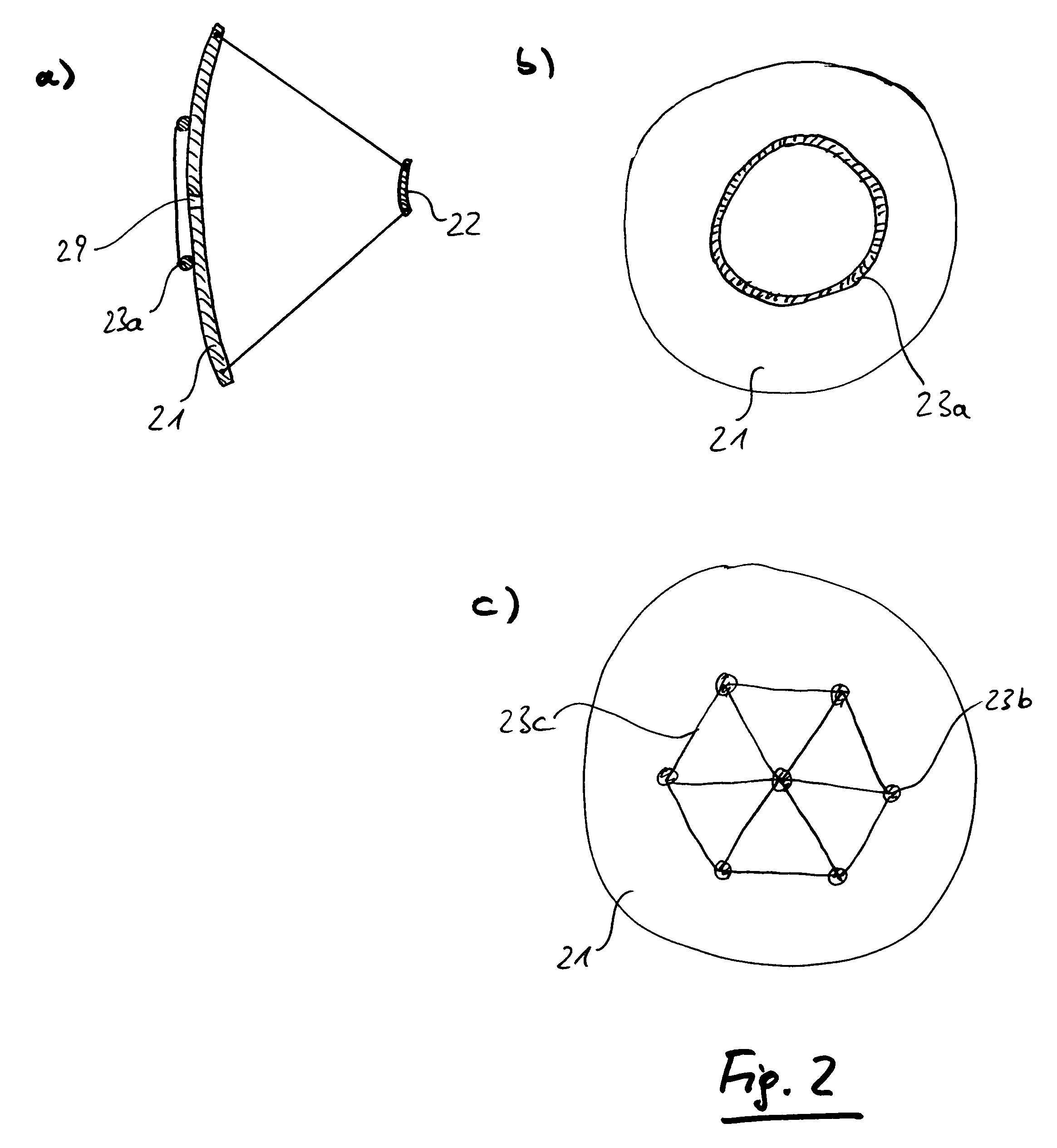
[0028]FIG. 1 is a schematical illustration of a free space optical communication link according to the present invention. A transmitter station (left side) and a receiving station (right side) each comprising an optical fibre network are connected by a free space communication link between transceivers 20 preferably using infrared light having a wavelength of about 1550 nm. The optical signal is coupled from the optical fibre network 30 through the optical fibre terminal 31 into the transceiver 20 comprising a primary mirror 21 and a secondary mirror 22. The optical signal is then transformed into a parallel light being having diameter of several ten centimeters. This large diameter is necessary in order to avoid potentially hazardous light intensities. The parallel light beam is then received by the receiving telescope 20 (in FIG. 1 on the right hand side). It is obvious that the transmission efficiency and so the maximum possible distance depends on an exactly parallel light beam....


PUM

PropertyMeasurementUnit
Temperatureaaaaaaaaaa

Abstract

Optical mirror elements for high bandwidth free space optical communication are produced by an electroforming replication technique. Onto the precision surface of a mandrel that is a negative of the required optical surface a layer of metal is deposited forming an exact copy of the mandrel surface and is then separated to form the required optical element. During the production process the mandrel may be coated with a variety of materials that are then separated together with the electroformed optical element during the release step to form a monolithic structure that includes a reflective coating. The mandrel remains unchanged by the process and can then be re-used. The high cost of conventional polishing techniques is therefore limited to the production of the mandrel. The replication process results in the production of low cost optical elements suitable for high bandwidth free space optical data transmission.

Description

BACKGROUND OF THE INVENTION[0001]The present invention relates to the use and manufacturing process of telescope mirrors for high bandwidth free space optical data transmission.[0002]The increased need for high bandwidth (high data rate) communication links induced by the recent growth of the internet and other telecommunication means lead to renowned interest in the free space optical data transmission (Whipple, “Free space communications connects”, Photonics at work, October 1999). In free space optical communications the data are transmitted through a communication link between a transmitting station to a receiving station by a laser being preferably having a frequency of about 1550 nm without using a physical medium like an optical fibre or the like. Depending on the weather conditions communication links over a distance of several kilometers with a bandwidth of up to 2.5 Gb / s have been demonstrated (P. F. Szajowski et al, “Key elements of high-speed WDM terrestrial free-space o...

Claims


Application Information

Patent Timeline
IPC IPC(8): G02B5/08C25D1/06C25D7/08G02B5/10G02B7/182
CPCC25D1/06C25D3/12C25D3/48C25D7/08G02B5/0808G02B17/0652Y10S359/90
Inventor VALENZUELA, ARNOLDOVALSECCHI, GIUSEPPEBANHAM, ROBERT DAVIDMARIONI, FABIO
Owner MEDIA LARIO SRL
Why Eureka
Try Eureka