Thermal barrier coating, manufacturing method thereof, turbine part and gas turbine

a technology of thermal barrier coating and manufacturing method, which is applied in the direction of wind motor components, non-positive displacement fluid engines, liquid fuel engine components, etc., can solve the problems of insufficient durability and peeling of ceramic layer comprising, and achieve excellent heat resistance and thermal cycle durability, excellent reliability

Active Publication Date: 2008-04-08
MITSUBISHI HITACHIPOWER SYST LTD
View PDF16 Cites 21 Cited by
  • Summary
  • Abstract
  • Description
  • Claims
  • Application Information

AI Technical Summary

Benefits of technology

[0009]The above-mentioned problem of peeling of the ceramics layer comprising YSZ is caused by the fact that the crystalline stability of YSZ is not sufficient in the high temperature environment and also is not sufficient in durability against a large thermal stress. Hence, in order to achieve the above-mentioned objects, the inventors here have carried out extensive studies on the construction of the thermal barrier coating for enhancing the crystalline stability and thermal cycle durability at the high temperature of the ceramics layer of the thermal barrier coating, and have obtained expertise to complete the present invention such that the durability of the thermal barrier coating can be enhanced by constructing the ceramics layer with ZrO2 stabilized by Yb2O3 or ZrO2 stabilized by Yb2O3 and Er2O3.
[0033]The present invention further provides a turbine part comprising a thermal barrier coating as mentioned in any one of the above-mentioned inventions as well as a gas turbine comprising this turbine part. According to the turbine part so constructed, a turbine part excellent in heat resistance and thermal cycle durability can be obtained and a gas turbine further excellent in reliability can be constructed.

Problems solved by technology

The above-mentioned problem of peeling of the ceramics layer comprising YSZ is caused by the fact that the crystalline stability of YSZ is not sufficient in the high temperature environment and also is not sufficient in durability against a large thermal stress.

Method used


Image

  • Thermal barrier coating, manufacturing method thereof, turbine part and gas turbine
  • Thermal barrier coating, manufacturing method thereof, turbine part and gas turbine
  • Thermal barrier coating, manufacturing method thereof, turbine part and gas turbine

Examples


first embodiment

A. First Embodiment

[0045](Layers of the Thermal Barrier Coating)

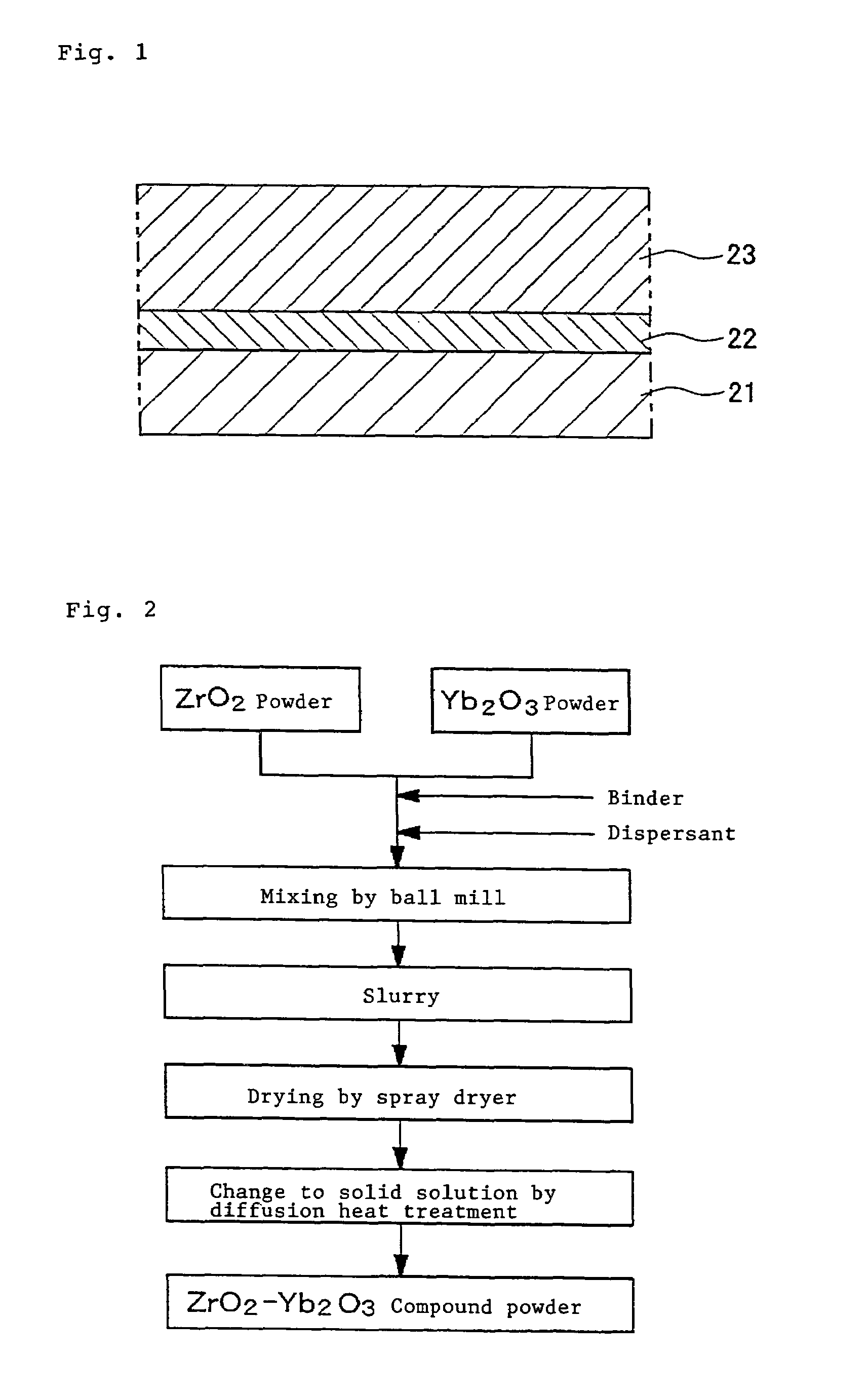
[0046]FIG. 1 is a view schematically showing a cross sectional structure of layers of a first embodiment of a thermal barrier coating according to the present invention. This thermal barrier coating is constructed such that a bond coat layer 22 comprising an MCrAlY alloy, etc. as a metallic bond layer excellent in corrosion resistance and oxidation resistance is laminated on a base material 21 of a high temperature heat resistant alloy for a moving blade, etc. and, further thereon, a ceramics layer 23 comprising ZrO2 partially stabilized by Yb2O3 (hereinafter referred to as “YbSZ”) as a top coat is laminated. Here, “M” of the MCrAlY alloy constructing the bond coat layer 22 means a metal element, for example, a single metal element of Ni, Co, Fe, etc. or a combination of two or more kinds of these metal elements.

[0047]The bond coat layer 22 has a function to lessen the difference in the thermal expansion coefficient bet...

second embodiment

B. Second Embodiment

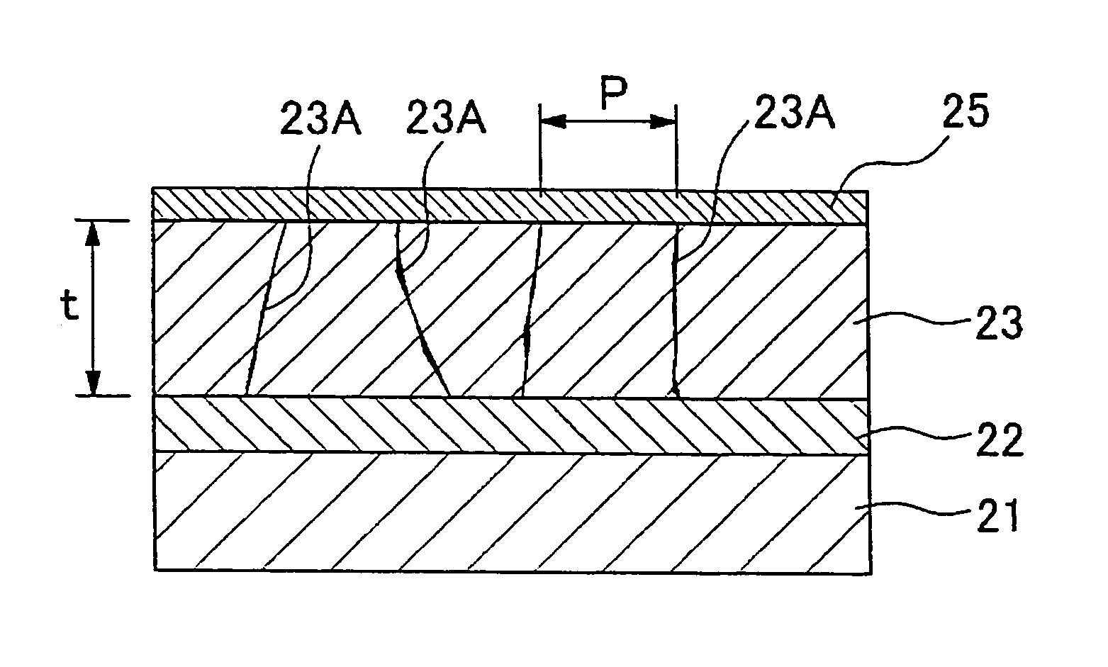
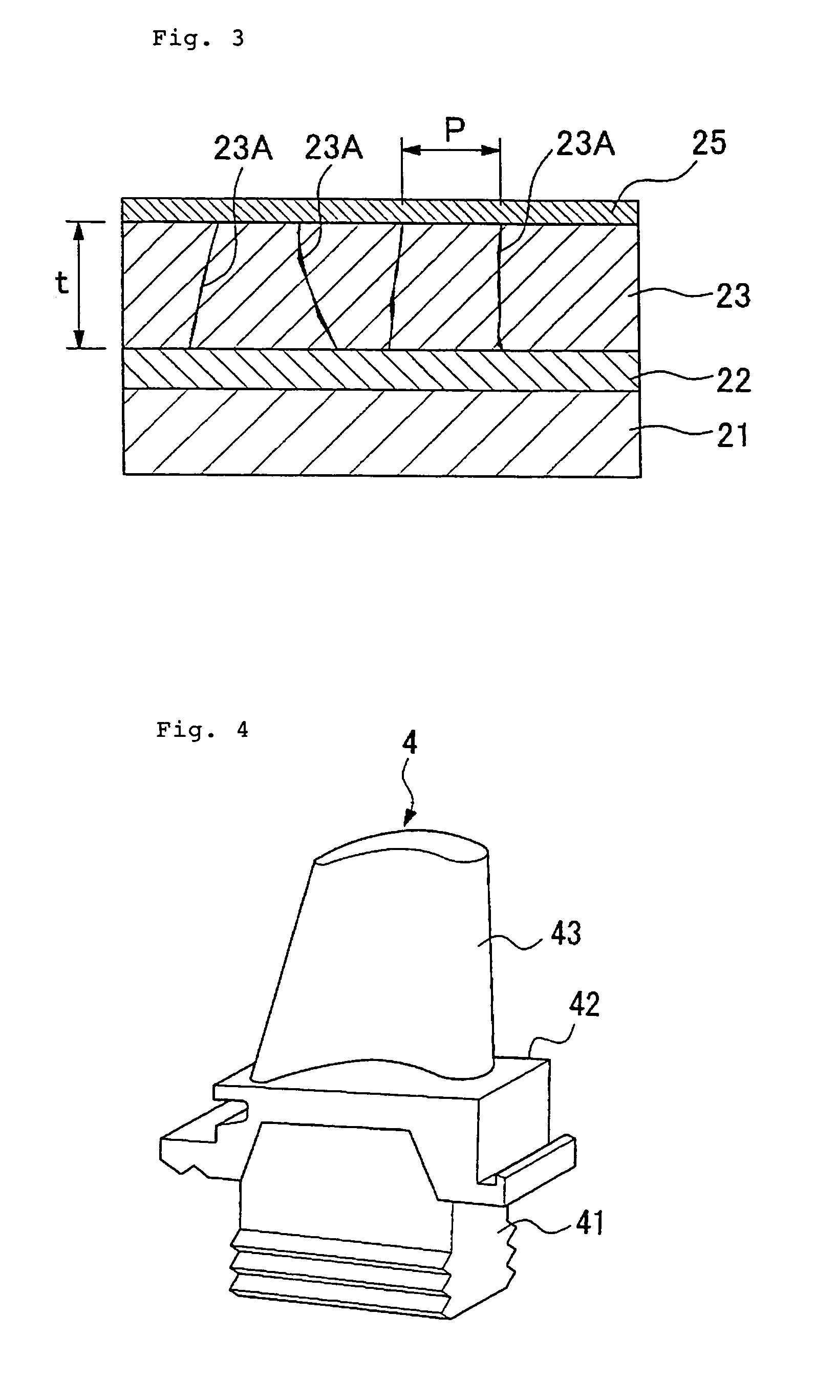
[0061]A second embodiment according to the present invention will be described with reference to FIG. 3. FIG. 3 is a view schematically showing a cross sectional structure of layers of a thermal barrier coating of the second embodiment according to the present invention. The same parts or components in FIG. 3 as those shown in FIG. 1 are designated by the same reference numerals and description thereon will be omitted. The thermal barrier coating of the second embodiment is likewise constructed such that the bond coat layer 22 is formed on the base material 21 of a heat resistant alloy and the ceramics layer 23 is laminated on this bond coat layer 22.

[0062]The difference of the thermal barrier coating of the present embodiment from the thermal barrier coating shown in FIG. 1 is that the ceramics layer 23 has a plurality of cracks 23A formed therein so as to elongate in the coating thickness direction, as shown in FIG. 3. These cracks 23A are intentionally introdu...

example 1

[0081]In the present example, in order to verify a change in the thermal cycle life corresponding to the addition quantity of Yb2O3, samples having a YbSZ layer in which a Yb2O3 addition quantity in ZrO2 is variously changed are formed and the thermal cycle life is measured. A base material used for forming the samples is a Ni base heat resistant alloy and the alloy composition is Ni—16Cr—8.5Co—1.7Mo—2.6W—1.7T—0.9Nb—3.4Al—3.4Ti. This base material has its surface applied with a grid blast treatment using Al2O3 grains and, thereon, a bond coat layer made of a CoNiCrAlY alloy having a composition of Co—32Ni—21Cr—8Al—0.5Y as a metal bond layer is formed by a low pressure plasma thermal spraying. A ceramics layer (YbSZ layer) is laminated on this bond coat layer of CoNiCrAlY by an atmospheric pressure plasma thermal spraying so that a thermal barrier coating is formed. A diffusion heat treatment temperature for making the ZrO2—Yb2O3 compound powder used for the thermal spraying of the Y...


PUM

PropertyMeasurementUnit
porosityaaaaaaaaaa
porosityaaaaaaaaaa
porosityaaaaaaaaaa

Abstract

A thermal barrier coating enabling to prevent peeling of layer in a high temperature use and still having a high thermal barrier effect, a turbine part coated by this thermal barrier coating and a gas turbine comprising this turbine part are provided. The thermal barrier coating comprises a base material 21 of high temperature heat resistant alloy and a ceramics layer 23 formed on the base material 21. The ceramics layer 23 comprises ZrO2 added with Yb2O3 as stabilizer and is laminated on the base material via a bond coat layer 22 laminated as a metallic bond layer. A plurality of cracks 23A are preferably introduced in the ceramics layer 23. The turbine part is constructed having its surface coated with the above thermal barrier coating.

Description

BACKGROUND OF THE INVENTION[0001]1. Field of the Invention[0002]The present invention generally relates to a thermal barrier coating that is excellent in the durability and a manufacturing method thereof and specifically relates to a construction of a ceramics layer used as a top coat of the thermal barrier coating. The present invention also relates to a turbine part using this thermal barrier coating and a gas turbine using this turbine part.[0003]2. Description of the Prior Art[0004]Recently, enhancement of the thermal efficiency of thermal power generation is being studied as one of energy saving measure. For enhancing the efficiency of a power generation gas turbine, elevating the gas inlet temperature is effective, and the temperature thereof sometimes becomes as high as about 1500° C. In order to realize such a high temperature of a power generation plant, it is necessary to use heat resistant parts and components in constructing stationary blades, moving blades, combustor wa...

Claims


Application Information

Patent Timeline
Patent Type & Authority Patents(United States)
IPC IPC(8): B32B9/00B32B15/04C23C4/10C23C28/00
CPCB32B15/04C23C4/105C23C28/3215C23C28/3455Y10T428/12618F05B2230/90F05C2253/12Y02T50/67C23C4/11Y02T50/60
Inventor TORIGOE, TAIJIMORI, KAZUTAKAAOKI, SUNAOTAKAHASHI, KOUJIOHARA, MINORU
Owner MITSUBISHI HITACHIPOWER SYST LTD
Why Eureka
Try Eureka