
Magnetic tunnel barriers and associated magnetic tunnel junctions with high tunneling magnetoresistance

a magnetic tunnel junction and tunnel barrier technology, applied in the field of magnetoresistive devices of magnetic tunnel junctions, can solve the problems of large self-demagnetization of devices, unwanted coupling fields in mtjs without a synthetic antiferromagnetic reference layer, etc., and achieve the effect of improving the performance of the tunnel barrier

Active Publication Date: 2008-04-15
INT BUSINESS MASCH CORP
View PDF52 Cites 16 Cited by
  • Summary
  • Abstract
  • Description
  • Claims
  • Application Information

AI Technical Summary

Benefits of technology

The approach achieves tunneling magnetoresistance values of at least 50% at room temperature, improving the performance and thermal stability of MTJs while reducing demagnetization fields and maintaining high spin polarization.

Problems solved by technology

This leads to very large self-demagnetizing for devices which are not circular in cross-section and very large magnetostatic coupling fields between ferromagnetic layers in the same device.
However, MTJs with MgO tunnel barriers and synthetic antiferromagnetic reference layers using Ru antiferromagnetic coupling layers do not exhibit the high tunneling magnetoresistance values exhibited by similar MTJs without the synthetic antiferromagnetic reference layer.
MTJs without a synthetic antiferromagnetic reference layer suffer from the presence of unwanted coupling fields, as discussed above, since the storage magnetic layer moment has a tendency to be aligned anti-parallel to the reference layer magnetic moment.

Method used


Image

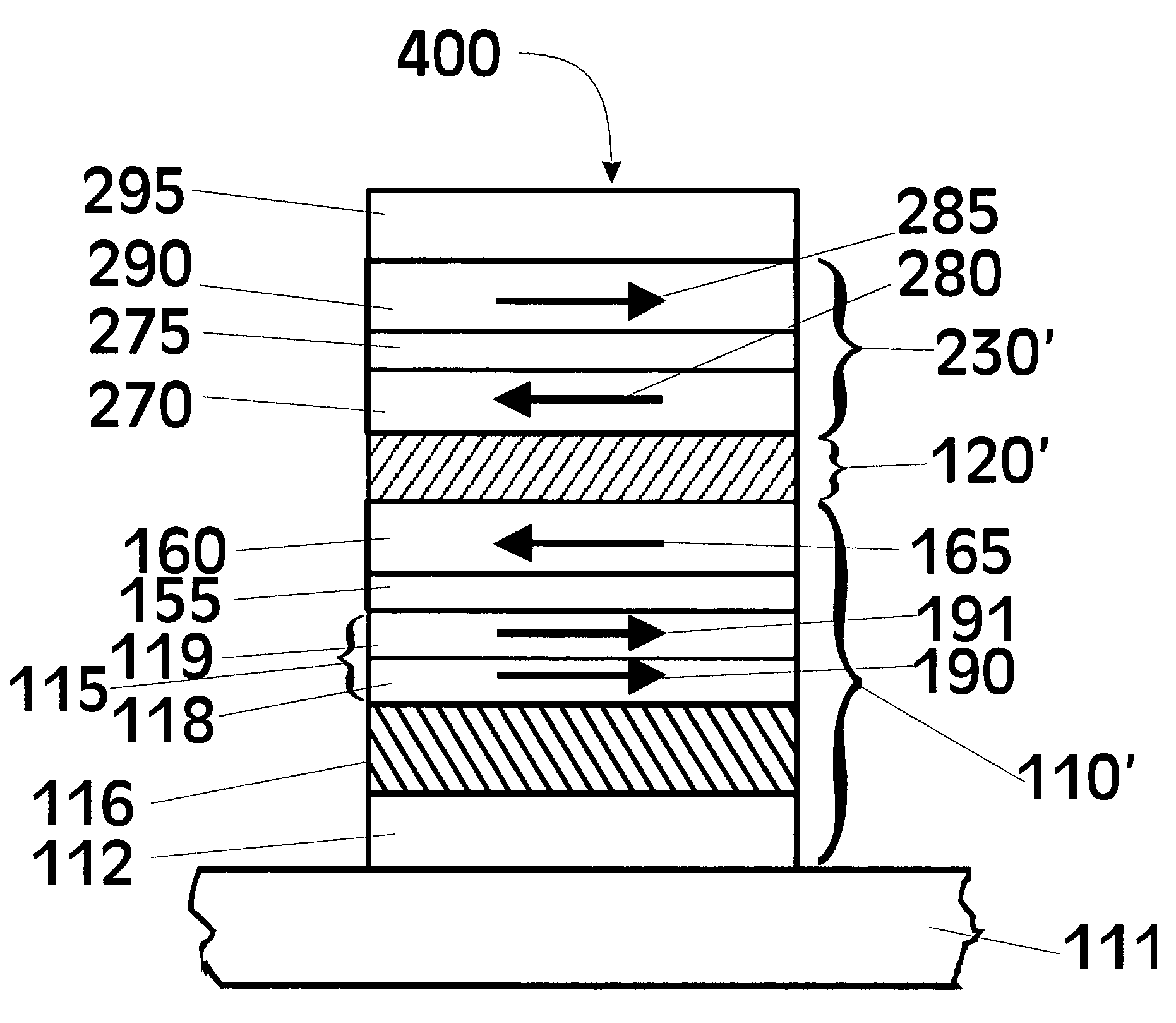
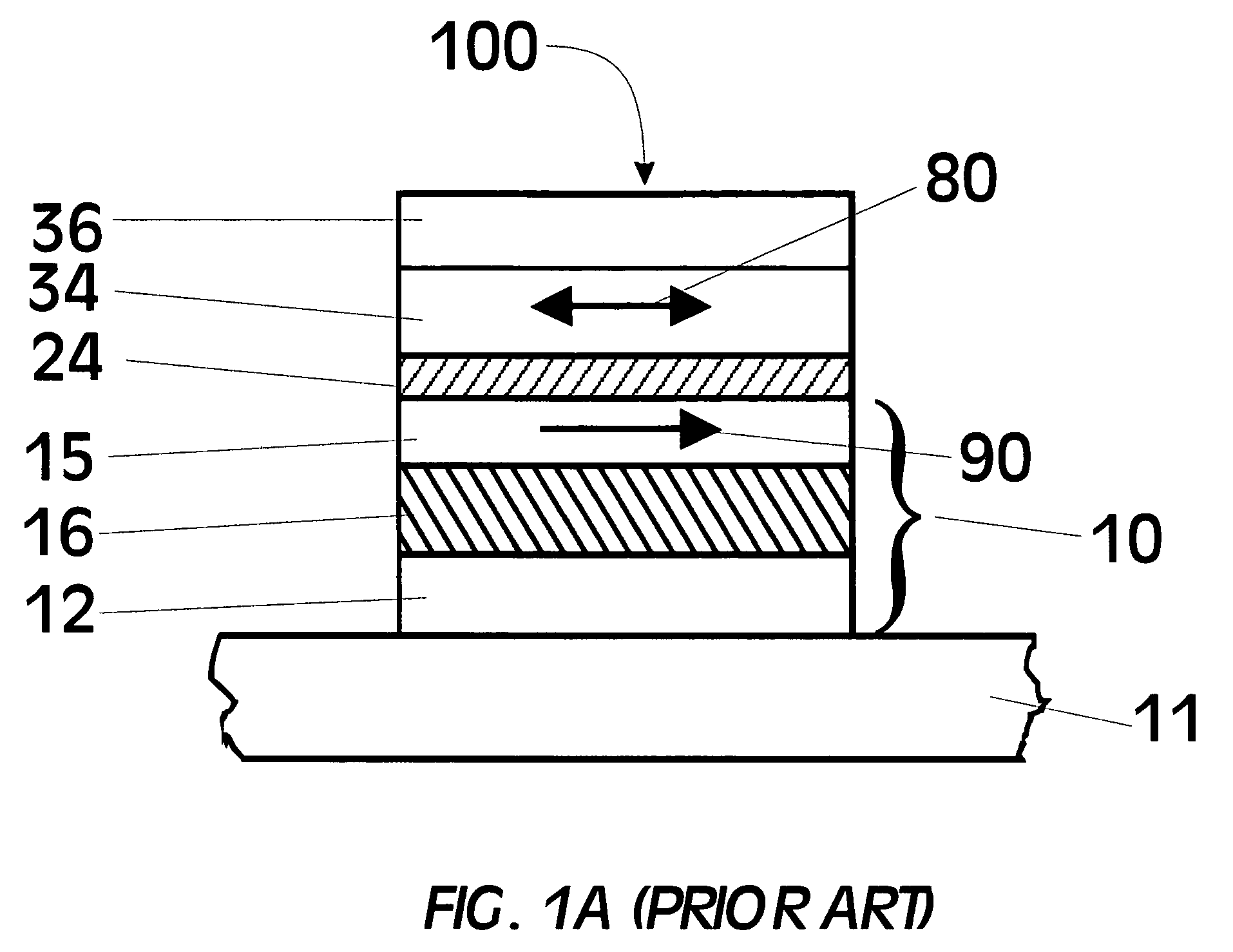
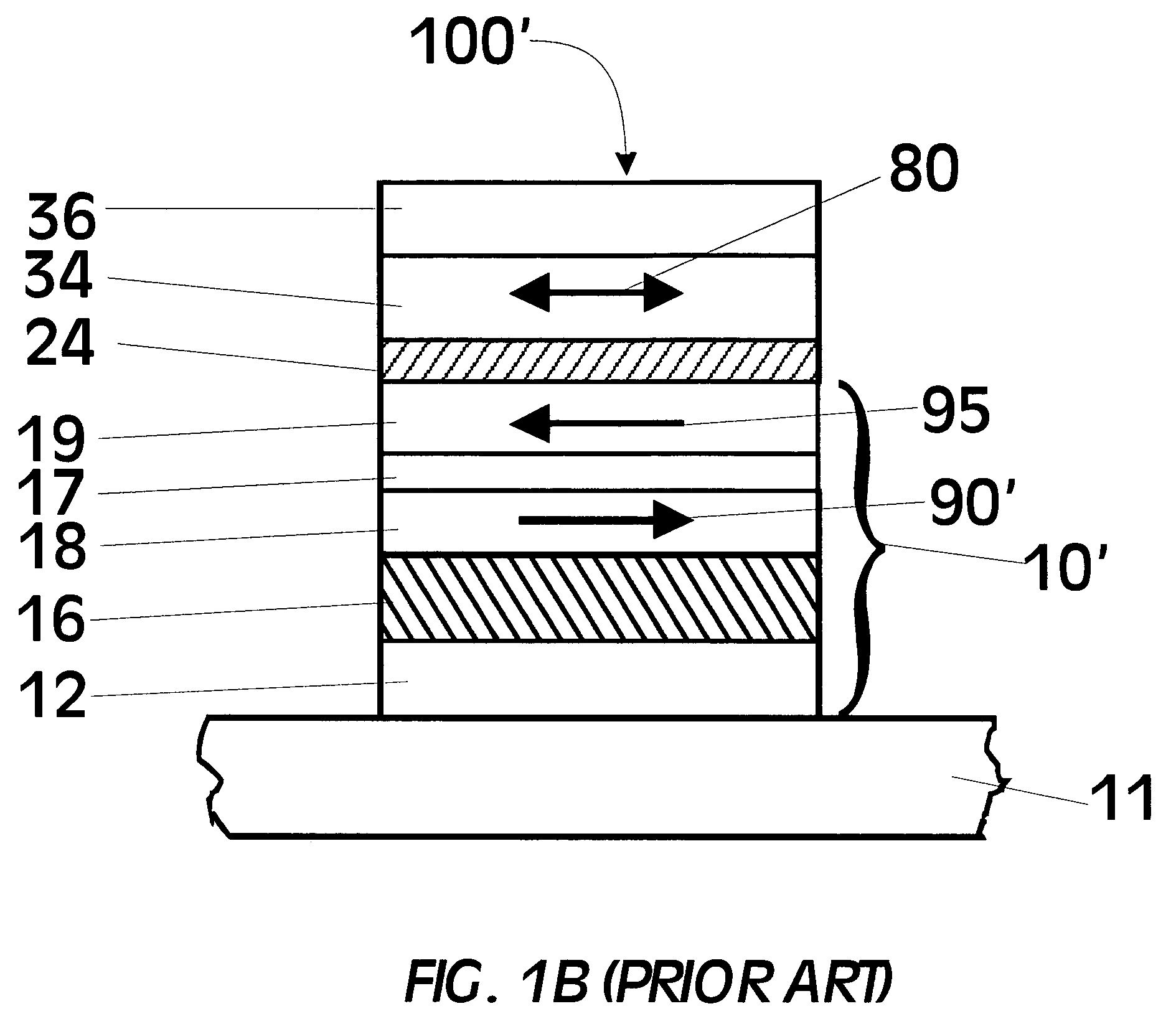
  • Magnetic tunnel barriers and associated magnetic tunnel junctions with high tunneling magnetoresistance
  • Magnetic tunnel barriers and associated magnetic tunnel junctions with high tunneling magnetoresistance
  • Magnetic tunnel barriers and associated magnetic tunnel junctions with high tunneling magnetoresistance

Examples


Embodiment Construction

[0040]The possibility of high tunneling magnetoresistance in MTJs formed from Fe / MgO / Fe sandwiches where the tunnel barrier is formed from crystalline (100) oriented MgO layers was theorized by W. H. Butler, X.-G. Zhang, T. C. Schulthess et al., Phys. Rev. B 63, 054416 (2001). However, extensive experimental work by many groups over a period of several years showed no evidence for improved tunneling magnetoresistance values using crystalline (100) MgO tunnel barriers as compared to amorphous alumina tunnel barriers. It was speculated that during the formation of the MgO tunnel barrier, the surface of the lower Fe electrode became oxidized perhaps resulting in much lower TMR than theorized. In U.S. patent application Ser. No. 10 / 824,835 to Parkin titled “MgO tunnel barriers and method of formation” (filed Apr. 14, 2004), supra, a method for forming MgO tunnel barriers is described which gives rise to MTJs which exhibit extraordinarily high values of tunneling magnetoresistance. To pr...


PUM

PropertyMeasurementUnit
thicknessaaaaaaaaaa
thicknessaaaaaaaaaa
thicknessaaaaaaaaaa

Abstract

Magnetic tunneling devices are formed from a first body centered cubic (bcc) magnetic layer and a second bcc magnetic layer. At least one spacer layer of bcc material between these magnetic layers exchange couples the first and second bcc magnetic layers. A tunnel barrier in proximity with the second magnetic layer permits spin-polarized current to pass between the tunnel barrier and the second layer; the tunnel barrier may be either MgO and Mg—ZnO. The first magnetic layer, the spacer layer, the second magnetic layer, and the tunnel barrier are all preferably (100) oriented. The MgO and Mg—ZnO tunnel barriers are prepared by first depositing a metallic layer on the second magnetic layer (e.g., a Mg layer), thereby substantially reducing the oxygen content in this magnetic layer, which improves the performance of the tunnel barriers.

Description

[0001]The U.S. Government has a paid-up license in this invention and the right in limited circumstances to require the patent owner to license others on reasonable terms as provided for by the terms of contract MDA972-99-C-0009 awarded by DARPA.TECHNICAL FIELD[0002]The invention relates to magnetic tunnel junction (MTJ) magnetoresistive (MR) devices for use as magnetic field sensors such as read heads for reading magnetically recorded data, as memory cells in nonvolatile magnetic random access memory (MRAM) cells, and for magnetic logic and spintronic applications. More particularly, this invention relates to an improved MTJ exhibiting high tunneling magnetoresistance with one or more electrodes formed from ferromagnetic layers coupled antiparallel to one another.BACKGROUND OF THE INVENTION[0003]The basic component of a magnetic tunnel junction is a sandwich of two thin ferromagnetic and / or ferrimagnetic layers separated by a very thin insulating layer through which electrons can t...

Claims


Application Information

Patent Timeline
Patent Type & Authority Patents(United States)
IPC IPC(8): G11B5/39G11B5/127
CPCB82Y10/00G01R33/093G01R33/098G11B5/3906G11B5/3909G11C11/16H01F10/3254H01F10/3272H01L43/08B82Y25/00Y10T428/1114H01F10/3295Y10T428/1107Y10T428/1121Y10T428/115Y10T428/1193H10N50/10
Inventor PARKIN, STUART STEPHEN PAPWORTH
Owner INT BUSINESS MASCH CORP
Learn More