Resonance method for production of intense low-impurity ion beams of atoms and molecules

a low-impurity ion and beam technology, applied in the direction of instruments, electric discharge lamps, material analysis, etc., can solve the problems of ineffective process at low particle velocities, high beam currents of parent elements, and substantial difficulty in extracting and transporting beams of such low-energy ions

Active Publication Date: 2008-04-29
VARIAN SEMICON EQUIP ASSOC INC
View PDF9 Cites 2 Cited by
  • Summary
  • Abstract
  • Description
  • Claims
  • Application Information

AI Technical Summary

Problems solved by technology

While commercial viability demands high beam currents to achieve useful production throughputs, the difficulties of extracting and transporting beams of such low-energy ions are substantial.
The fundamental problem is the introduction and maintenance of an adequate number of space-charge neutralizing electrons or negative ions within the ion beam to avoid beam ‘blow-up’.
Unfortunately, this process becomes ineffective at low particle velocities and other techniques must be used.
A central problem for detecting radioactive atoms at such low abundance is that high beam currents of the parent element are essential.
As a consequence, while negative ions are quite ubiquitous, for those species where the electron affinity is small, the ion production rate from a sputter source may be so low that the beam is useless for many measurements.
These changes have led to increases in electrical capacitance between elements that may cause parasitic current-coupling between individual circuits that can cause circuit instabilities.
Unfortunately, the cross section for the necessary negative ion production tends to be small and it is this limitation of the tandem-type acceleration system that often restricts beam-current intensity.
However, those skilled in the art will recognize that D is not well defined and that resonant cross sections will not change abruptly but will fall smoothly as the differential ionization energy increases.
As the goal of the experiment was production of high-energy Ca− ions for nuclear physics measurements and an ion current of one microampere was more than adequate, no efforts were made to increase the output current above this value.
However, high intensity beams (greater than 1 milli-ampere?) have not previously been produced.

Method used


Image

  • Resonance method for production of intense low-impurity ion beams of atoms and molecules
  • Resonance method for production of intense low-impurity ion beams of atoms and molecules
  • Resonance method for production of intense low-impurity ion beams of atoms and molecules

Examples


Embodiment Construction

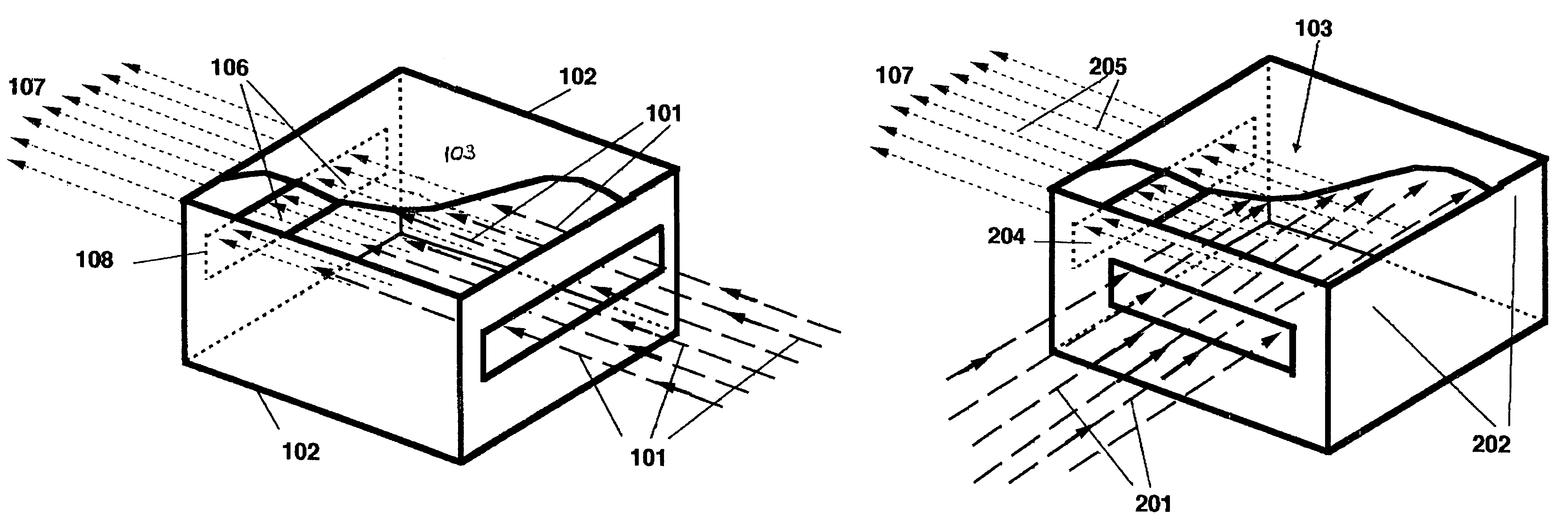
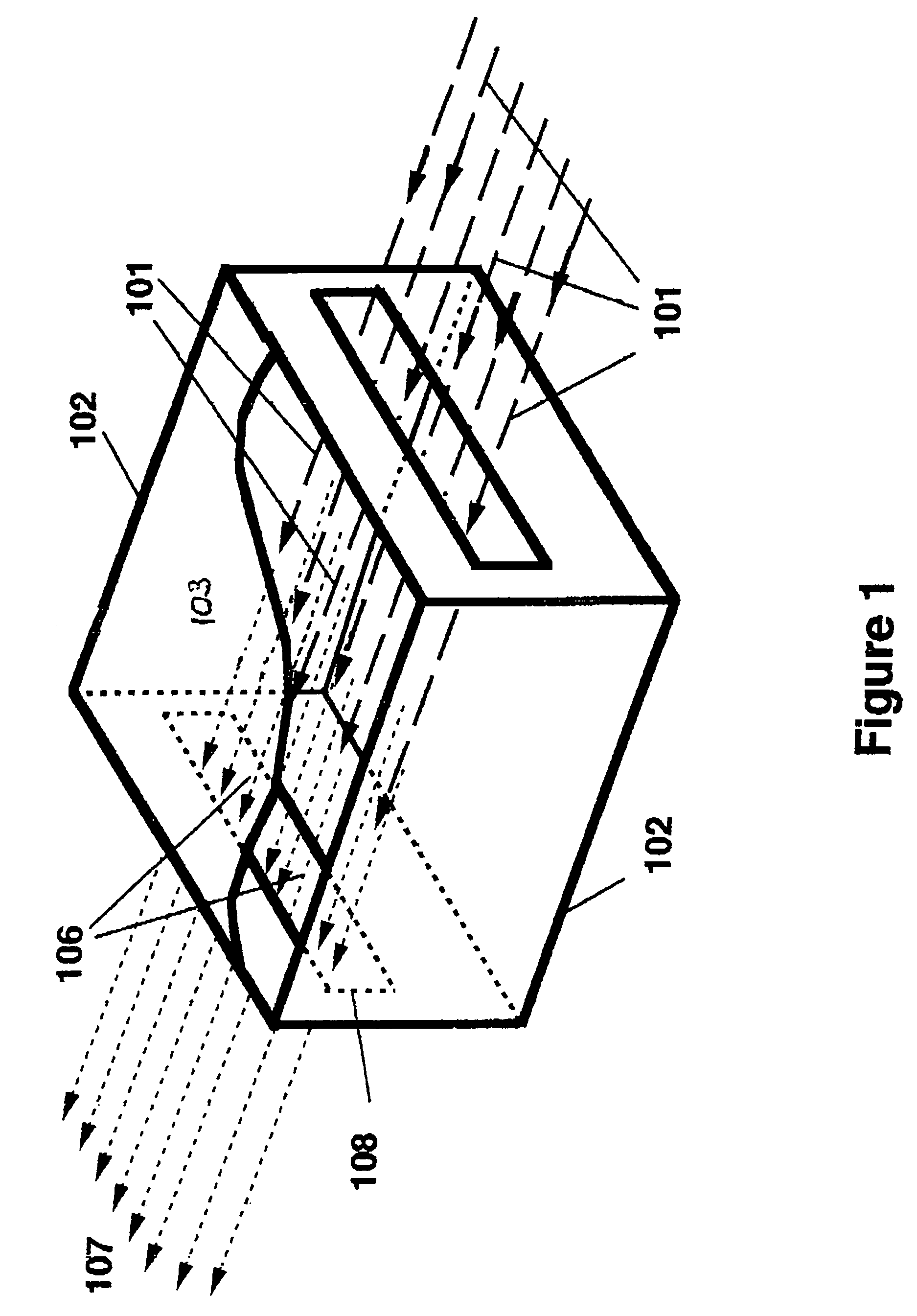
[0038]Referring to the drawings, and first to FIG. 1 thereof, therein is shown a primary ion beam, 101, entering a cell, 102, and passing through a gas or vapor, 103, contained within the cell. Either negative or positive ions can be used as the primary ion beam, 101, which can be either atomic or molecular. Within the cell, 102, the sample, 103, is maintained in a gaseous or vapor form at an appropriate vapor pressure. If necessary, temperature control may be needed using suitable heaters or refrigerators. The primary ion beam species, 101, is chosen so that the electron affinity or ionization potential of the ion species, 101, is approximately equal to the electron affinity or ionization potential of the atom or molecule comprising the gas or vapor, 103, that is to be converted to negative or positive ions. The resulting ions, 106, are extracted longitudinally from the opposite side of the cell from that where the primary ion beam enters and is formed into a suitable ion beam, 107...


PUM


Abstract

The present invention comprehends a compact and economical apparatus for producing high intensities of a wide variety of wanted positive and negative molecular and atomic ion beams that have been previously impossible to previously produce at useful intensities. In addition, the invention provides a substantial rejection of companion background ions that are frequently simultaneously emitted with the wanted ions. The principle underlying the present invention is resonance ionization-transfer where energy differences between resonant and non-resonant processes are exploited to enhance or attenuate particular charge-changing processes. This new source technique is relevant to the fields of Accelerator Mass Spectroscopy; Molecular Ion Implantation; Generation of Directed Neutral Beams; and Production of Electrons required for Ion Beam Neutralization within magnetic fields. An example having commercial importance is ionization of the decaborane molecule, B10H14 where an almost perfect ionization resonance match occurs between decaborane molecules and arsenic atoms.

Description

[0001]This applications claims the benefit of domestic priority based on U.S. Provisional Application Ser. No. 60 / 683,016, entitled “A Resonance Method for Producing Intense beams of Molecular Ions”, filed May 20, 2005; the disclosure of which is hereby incorporated by reference.FIELD OF THE INVENTION[0002]Accelerator mass spectroscopy, isotope dating, high-energy semiconductor implantation, low-energy semiconductor ion implantation, molecular beam implantation, cluster beam ionization, decaborane ionization, isobaric particle rejection.BACKGROUND OF THE INVENTION[0003]The technique to be described has important applications in several fields of scientific research and in industry. These include molecular ion implantation; the generation of directed neutral beams; the production within magnetic fields of low-energy electrons required for ion beam neutralization; the attenuation of unwanted isobars during accelerator mass spectroscopy (AMS) measurements. Such processes will be briefl...

Claims


Application Information

Patent Timeline
Patent Type & Authority Patents(United States)
IPC IPC(8): H01J7/24
CPCH01J37/08H01J37/3171H01J49/145H05H3/02H01J2237/0815H01J2237/31705
Inventor PURSER, KENNETH H.LITHERLAND, ALBERT E.TURNER, NORMAN L.
Owner VARIAN SEMICON EQUIP ASSOC INC
Why Eureka
Try Eureka