Optical system for measuring samples using short wavelength radiation

a technology of optical systems and wavelength radiation, applied in the direction of optical radiation measurement, photometry using electric radiation detectors, instruments, etc., can solve the problems of low throughput of systems, and high cost of building, so as to reduce the attenuation of wavelength components such as vuv radiation, reduce the attenuation of vuv radiation, and enhance the system throughput

Active Publication Date: 2008-05-06
KLA TENCOR TECH CORP
View PDF15 Cites 65 Cited by
  • Summary
  • Abstract
  • Description
  • Claims
  • Application Information

AI Technical Summary

Benefits of technology

[0009]This invention is based on the recognition that, by reducing the amount of ambient absorbing gas or gases and moisture present in at least a portion of the illumination and detection paths experienced by vacuum ultraviolet (VUV) radiation used in the measurement process, the attenuation of such wavelength components can be reduced. Such reduction can be accomplished by a process without requiring the evacuation of all gases and moisture from the measurement system. In one embodiment, the reduction can be accomplished by displacing at least some of the absorbing gas(es) and moisture present in at least a portion of the measuring paths so as to reduce the attenuation of VUV radiation. In this manner, the sample does not need to be placed in a vacuum or purged gas, thereby enhancing system throughput.
[0010]In one embodiment, the measurement system may be placed in a gas medium which contains less VUV absorbing gas(es) and moisture compared to an atmosphere surrounding the measurement system. Preferably, the gas medium is continually or continuously supplied by a source of gas that does not substantially absorb VUV radiation. In a preferred embodiment, this gas medium is maintained within an enclosure having an opening adjacent to the sample that is being measured. Preferably, the gas medium is maintained at a higher pressure compared to the ambient pressure so that the gas medium escaping through the opening reduces the amount of absorbing gas(es) and moisture that may otherwise be present in at least a portion of the measurement path of the VUV radiation passing through the opening between the measurement system, the sample and the detector. Also preferably, the opening is of such shape and size as to permit radiation to be incident on the sample at a range of different angles and enhances laminar flow of the gas through the opening while reducing turbulence, since turbulence may cause measurement errors.
[0011]To further reduce turbulence, preferably the region of the opening is shielded from the atmosphere, such as by another gas flow or an obstruction, so that the pressure differential that is maintained across the opening can be reduced. This further enhances laminar flow of the gas through the opening and reduces turbulence.

Problems solved by technology

Vacuum or fully purged gas measurement systems, however, are expensive to build.
Furthermore, since the sample that is measured is also placed in the vacuum or purged gas, such systems typically have low throughput and are not suitable in manufacturing monitoring.

Method used


Image

  • Optical system for measuring samples using short wavelength radiation
  • Optical system for measuring samples using short wavelength radiation
  • Optical system for measuring samples using short wavelength radiation

Examples


Embodiment Construction

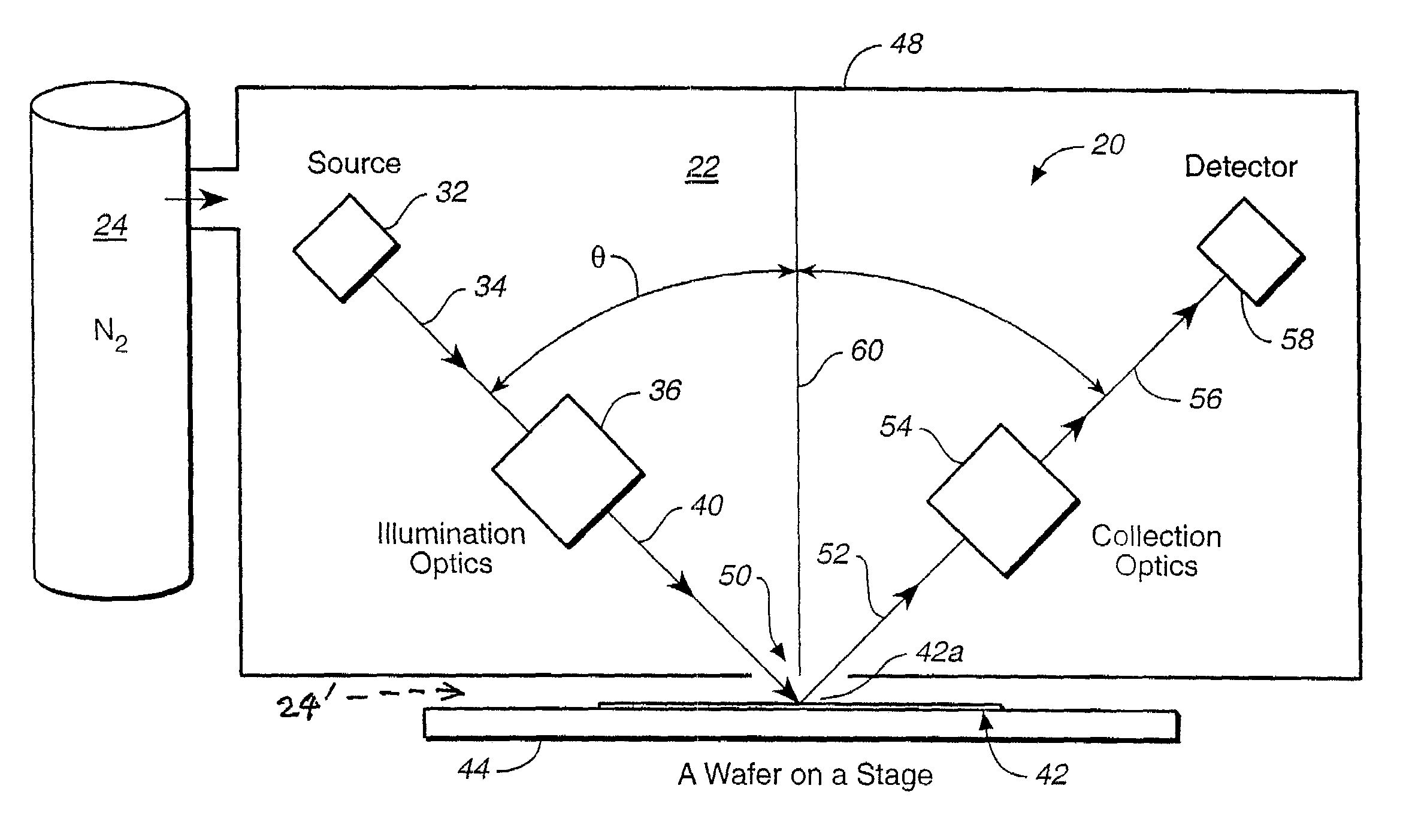
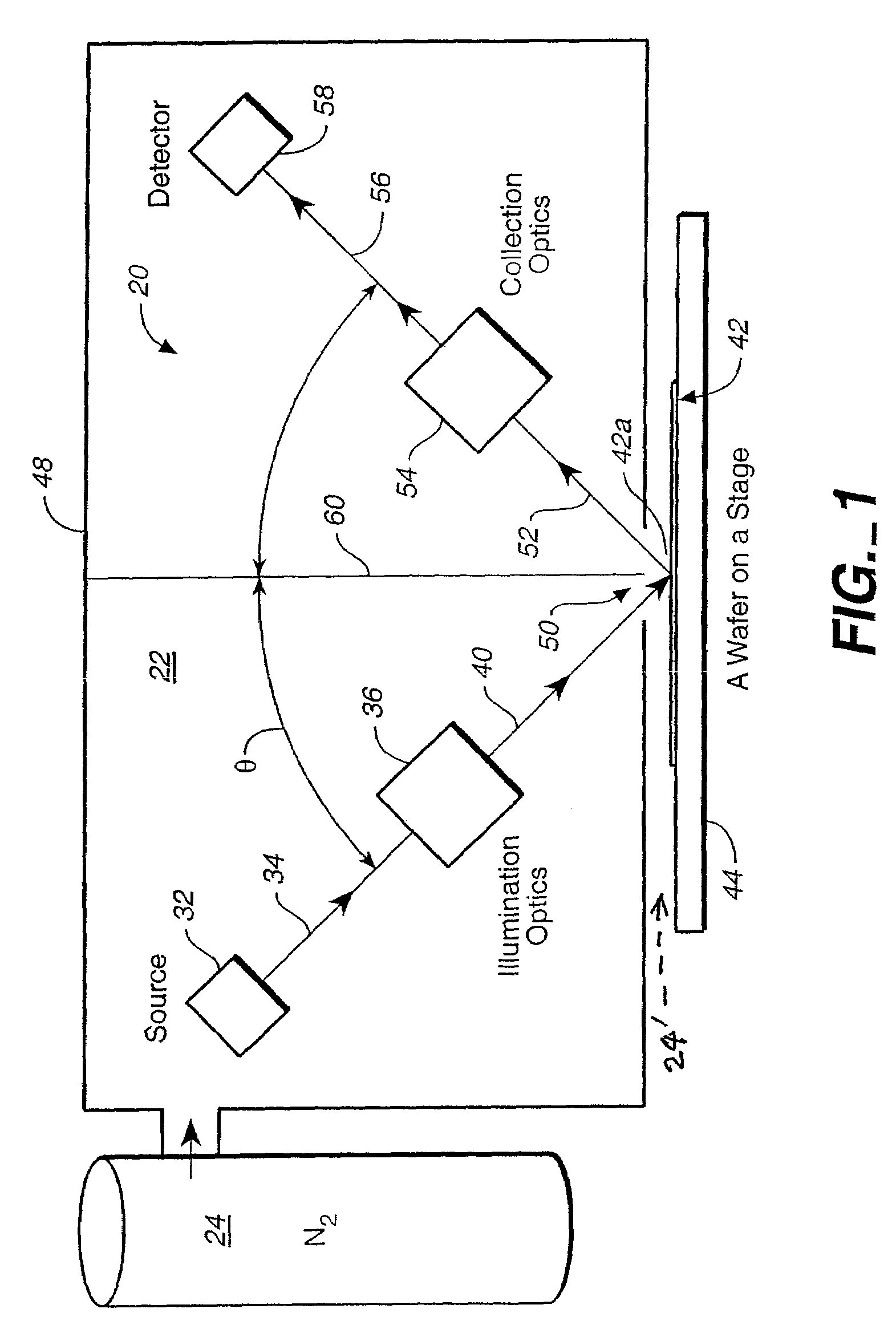
[0032]FIG. 1 is a schematic view of a measurement system for measuring characteristics of a sample such as a semiconductor wafer to illustrate one embodiment of the invention. As shown in FIG. 1, the optical measurement system 20 is placed inside an envelope 48. Hence, most of the optical beam path in system 20 is placed within a gas medium 22 that contains less moisture and absorbing gas with respect to VUV radiation compared to that in the ambient environment. In one embodiment, the gas medium 22 in envelope 48 comprises a nitrogen gas supplied by a nitrogen source 24 (which supplies a nitrogen gas that contains substantially no VUV absorbing gases such as oxygen and moisture). It will be understood that one or more other gases such as helium, argon, neon or another inert gas may be used instead or in combination with or without nitrogen and are within the scope of the invention. Preferably, the source supplies nitrogen gas to displace substantially all of the air and moisture tha...


PUM

PropertyMeasurementUnit
wavelengthaaaaaaaaaa
wavelengthsaaaaaaaaaa
distanceaaaaaaaaaa

Abstract

In an optical system measuring sample characteristics, by reducing the amount of ambient absorbing gas or gases and moisture present in at least a portion of the illumination and detection paths experienced by vacuum ultraviolet (VUV) radiation used in the measurement process, the attenuation of such wavelength components can be reduced. Such reduction can be accomplished by a process without requiring the evacuation of all gases and moisture from the measurement system. In one embodiment, the reduction can be accomplished by displacing at least some of the absorbing gas(es) and moisture present in at least a portion of the measuring paths so as to reduce the attenuation of VUV radiation. In this manner, the sample does not need to be placed in a vacuum, thereby enhancing system throughput.

Description

CROSS-REFERENCE TO RELATED APPLICATIONS[0001]This application claims the benefit of U.S. Provisional Patent Application No. 60 / 429,441 filed on Nov. 26, 2002, which application is incorporated herein by reference.BACKGROUND OF THE INVENTION[0002]This invention relates in general to optical systems for measuring characteristics of a sample, and in particular to such system using radiation that contains a vacuum ultraviolet wavelength component.[0003]For a number of industrial applications, it is useful to determine the surface metrology of samples such as thicknesses of thin films, their refractive indices and the profile parameters of surface features such as gratings on semiconductor wafers. These characteristics may be determined by a number of techniques. Among the better known non-destructive testing techniques are those of spectroreflectometry, spectroscopic ellipsometry and scatterometry.[0004]With the shrinking of semiconductor devices to smaller and smaller geometries, the s...

Claims


Application Information

Patent Timeline
Patent Type & Authority Patents(United States)
IPC IPC(8): G01N21/17G01N21/88G01N21/95
CPCG01N21/8806G01N21/9501
Inventor NIKOONAHAD, MEHRDADLEE, SHINGKWAK, HIDONGEDELSTEIN, SERGIOZHAO, GUOHENGJANIK, GARY
Owner KLA TENCOR TECH CORP
Why Eureka
Try Eureka