Method of forming fluoropolymer binders for carbon nanotube-based transparent conductive coatings

a technology of carbon nanotubes and conductive coatings, applied in the direction of electrical apparatus casings/cabinets/drawers, non-metal conductors, paper/cardboard containers, etc., can solve the problems of poor abrasion resistance and flexibility of ito-based coatings and films, limited supply of expensive indium, and limited polymer conductivity and optical transparency

Inactive Publication Date: 2008-05-27
EIKOS
View PDF4 Cites 71 Cited by
  • Summary
  • Abstract
  • Description
  • Claims
  • Application Information

AI Technical Summary

Benefits of technology

[0024]Another embodiment of the invention is directed to a method of increasing the conductivity of a conductive film comprising applying a layer of carbon nanotubes to a surface to form a conductive film; applying another layer of material to said carbon nanotube layer that compresses said carbon nanotubes and increases sheet conductivity across a surface of said conductive film, preferably wherein the another layer contains a fluoropolymer or fluoromonomer binder.

Problems solved by technology

However, ITO-based coating and film have inferior abrasion resistance and flexibility.
The supply of expensive indium is also very limited.
However, polymer conductivity and optical transparency are limited.
Despite good flexibility, abrasion resistance is also very poor.
The challenges for this approach include difficulty in uniform mixing due to bundles and agglomeration of CNT, and difficulty in achieving very high conductivity due to an insulative nature of polymers.
However, these coated substrates often do not have extremely high adhesion and abrasion resistance.
A disadvantage is that the acrylic top coating also serves to electrically insulate the coated surface, making contact to the conductive ITO difficult or impossible.
Since most commercially available transparent conductive coatings and films are solid materials, the addition of other layers typically interferes with this function of surface conductivity.
The disadvantage to this approach is that in these composite coatings, conductivity is greatly reduced by the presence of polymeric resins which serve to dilute and interrupt the conductive pathways.

Method used


Image

  • Method of forming fluoropolymer binders for carbon nanotube-based transparent conductive coatings
  • Method of forming fluoropolymer binders for carbon nanotube-based transparent conductive coatings
  • Method of forming fluoropolymer binders for carbon nanotube-based transparent conductive coatings

Examples


example 1

#CE1: CNT / glass

[0139]The dispersion of SWNT in 3:1 IPA / water was sprayed onto a cleaned and dried glass slide (1×3″), which had been coated with gold by sputtering at both ends as the electrodes. This sample showed a stable Rs value of 667 O / C= after being in the desiccator for 16-24 hrs. The transmittance of the CNT coating at wavelength of 550 nm is 90-91% % (which can be in the range of 92-95% when a better grade of ink is used). This number is used as the baseline value for further comparison. When this sample was exposed to relative humidity level of 9%, the Rs value initially quickly dropped to 580 Ω / C= within 6 minutes and then quickly increased. After being stabilized, the Rs value of 688 Ω / C= was observed. Compared to the baseline in dry (RH 0%) condition, the Rs value increased by 3.15% at this relative humidity level (RH 9%).

[0140]Similarly, the stable Rs values were 850 Ω / C= and 1600 Ω / C=, corresponding to exposure to the humidity conditions of RH 43% and 75% for 24 hour...

example 2

#CE2: CNT / PET

[0145]The dispersion of SWNT in 3:1 IPA / water was sprayed onto a PET film (Melinex ST 505 from Dupont-Teijin). The sample was then cut into 6×8 cm in size with the both ends pasted with conductive silver paste for further testing. Typical Rs value was in the range of 500-600 Ω / C= while optical transmittance value of this CNT network coating at 550 nm was 89-90% (which was in the range of 91-94% when a better grade of CNT ink was used). Results using similar screening methods are shown in Table 1.

[0146]CNT / substrate with Polymer Binders

example 3

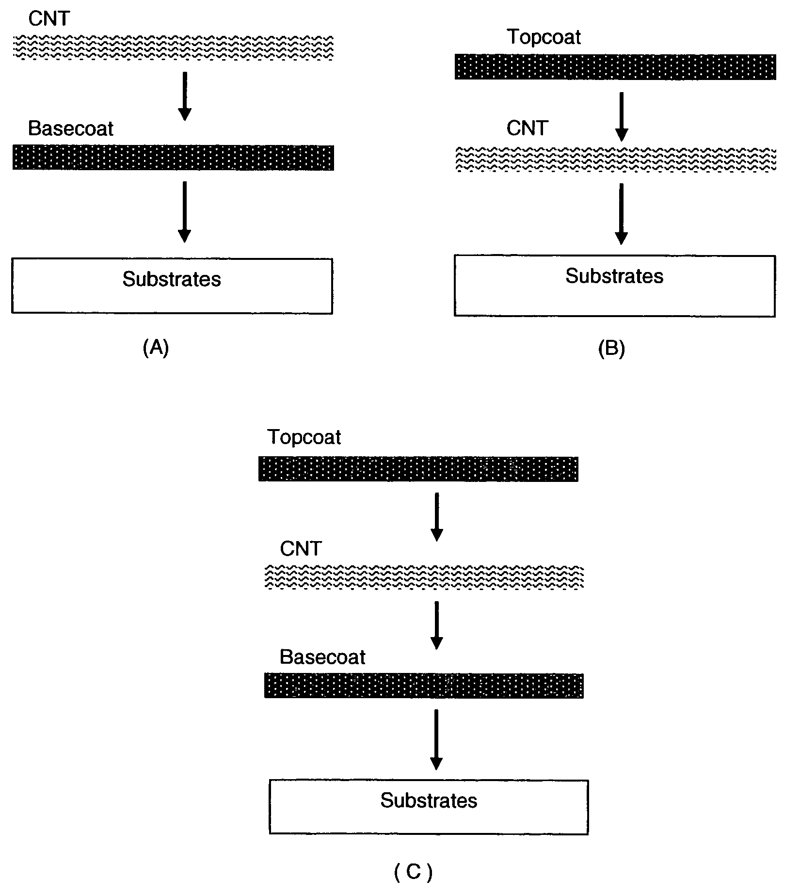
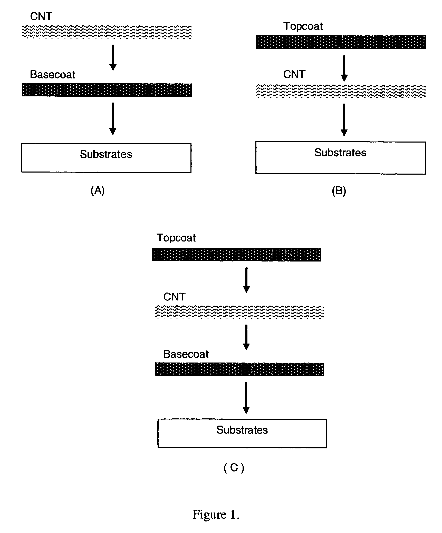
#WE 1: CNT / glass with PVDF as the Binder (Topcoat)

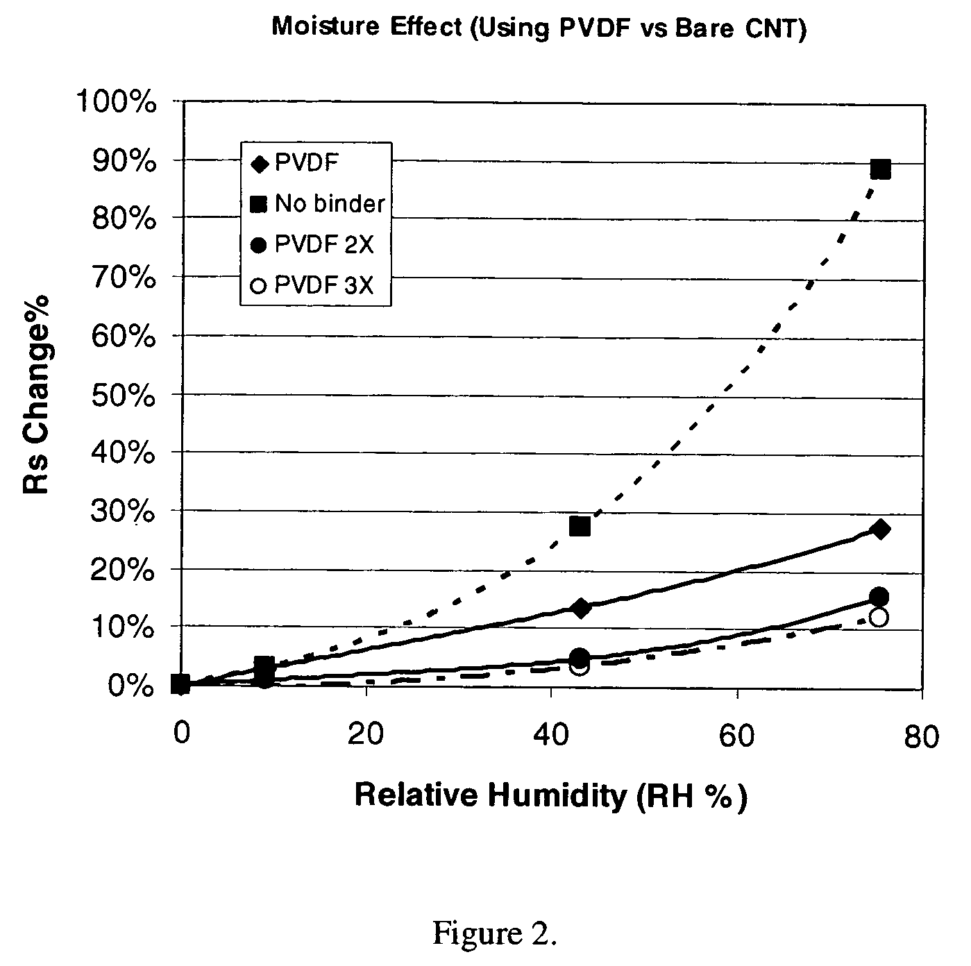
[0147]By using the same ink used for the comparative examples, the sample of CNT / glass were made. It was then dip-coated with 1% of polyvinylidiene fluoride (PVDF) solution dissolved in N,N-dimethyl acetamide followed by drying, and then tested for moisture resistance in the same way as described. The sample was also coated with PVDF multiple times for better coating quality and higher thickness. The sample was tested each time after coating. The results are shown in FIG. 2, FIG. 3 and Table 2.

[0148]Initially the sample showed Rs of 630 Ω / C= at ambient conditions. Stable Rs values of the sample with 1×PVDF coating are 720 and 919 Ω / C=, corresponding to RH 0 and 75%, respectively. The change in Rs from the dry state to RH 75% is 27.5%. After twice (2×) coating, stable Rs values are 720 and 833 Ω / C=, corresponding to RH 0 and 75%, respectively. The change from the dry state to RH 75% is 15.7%. After coating 3×, stable Rs values are 716...


PUM

PropertyMeasurementUnit
transmittanceaaaaaaaaaa

Abstract

This invention relates to flexible, transparent and conductive coatings and films formed using carbon nanotubes (CNT) and, in particular, single wall CNT, with polymer binders. Preferably, coatings and films are formed from CNT applied to transparent substrates forming one or multiple conductive layers at nanometer level of thickness. Polymer binders are applied to the CNT network coating having an open structure to provide protection through infiltration, and may comprise a basecoat, a topcoat, or a combination thereof, providing enhanced optical transparency, conductivity, moisture resistance, thermal resistance, abrasion resistance and interfacial adhesion. Polymers may be thermoplastics, thermosets, insulative, conductive or a combination thereof. A fluoropolymer containing binder is applied onto a CNT-based transparent conductive coating at nanometer level of thickness on a clear substrate. The fluoropolymers or blend can be either semi-crystalline or amorphous. This binder coating and the resulting products can be used for display and electronic applications.

Description

REFERENCE TO RELATED APPLICATIONS[0001]This application claims priority to U.S. Provisional Application No. 60 / 600,389 entitled “Fluoropolymer Binders for Carbon Nanotube-Based Transparent Conductive Coatings” filed Aug. 11, 2004, and U.S. application Ser. No. 11 / 014,233 entitled “Polymer Binders for Flexible and Transparent Conductive Coatings having Carbon Nanotubes, and Corresponding Construction Structures, Processes and Articles” filed Dec. 17, 2004, which claims priority to U.S. Provisional Application No. 60 / 529,735 of the same title filed Dec. 17, 2003, and U.S. Provisional Application No. 60 / 549,159 entitled “Transparent Conductive Coatings having High and Stable Performance Including Moisture, Heat, Abrasion and Bending Resistance” filed Mar. 3, 2004, all of which are entirely and specifically incorporated by reference.GOVERNMENT INTERESTS[0002]This invention was made, in part, with government support under Contract No. Fa8650-04-C-5702 awarded by the United States Air For...

Claims


Application Information

Patent Timeline
Patent Type & Authority Patents(United States)
IPC IPC(8): H01B1/00C08J7/043C08J7/044C08J7/046
CPCB82Y10/00C08J7/045H01B1/24Y10T156/10C08J2427/12C08J2367/02C08J7/0423C08J7/043C08J7/046C08J7/044
Inventor LUO, JIAZHONGARTHUR, DAVID J.GLATKOWSKI, PAUL J.
Owner EIKOS
Why Eureka
Try Eureka