Adjustment method of rotor position detection of synchronous motor

a technology of synchronous motor and adjustment method, which is applied in the direction of motor/generator/converter stopper, electronic commutator, dynamo-electric converter control, etc., can solve the problems of expensive equipment adopting this method, and achieve the effects of improving the positioning accuracy of the rotational position detector, good performance and excellent productivity

Active Publication Date: 2008-06-17
MITSUBISHI ELECTRIC CORP
View PDF10 Cites 8 Cited by
  • Summary
  • Abstract
  • Description
  • Claims
  • Application Information

AI Technical Summary

Benefits of technology

[0010]According to the adjustment method of rotor position detection of a synchronous motor of the present invention, it can obtain a synchronous motor with good performance by stabilizing and improving positioning accuracy of a rotational position detector and to obtain an adjustment method of rotor position detection of a synchronous motor with excellent productivity. In particular, since the amount of deviation is detected while rotating, an average value of the amount of deviation can be obtained and the detection accuracy of the amount of deviation can be improved. Further, as seen from an earlier application to be described later, the method can be simplified by eliminating extra work, such as when DC energization is applied to a stator to constrain a rotor.
[0011]Further, a no-load detector and a motor voltage detector are not required and a deviation of a rotational position of a rotational position detector can be corrected.

Problems solved by technology

In the above described conventional method of correcting the deviation generated between the rotational position of a synchronous motor determined from the output of the rotational position detector and the actual rotational position of the synchronous motor, since a motor voltage detector and a no-load detector must be provided, an apparatus adopting this method becomes expensive.

Method used


Image

  • Adjustment method of rotor position detection of synchronous motor
  • Adjustment method of rotor position detection of synchronous motor
  • Adjustment method of rotor position detection of synchronous motor

Examples


embodiment 1

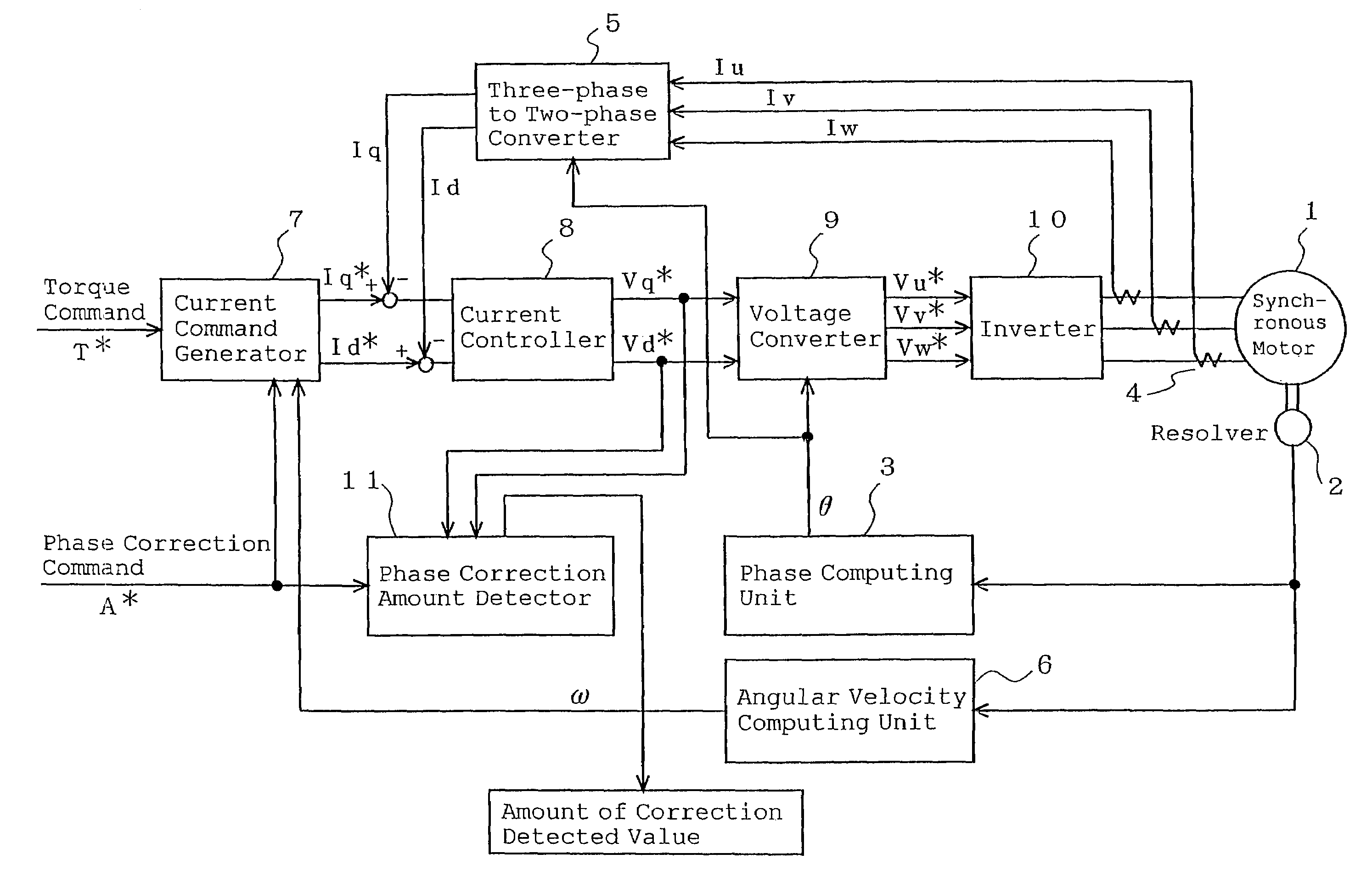
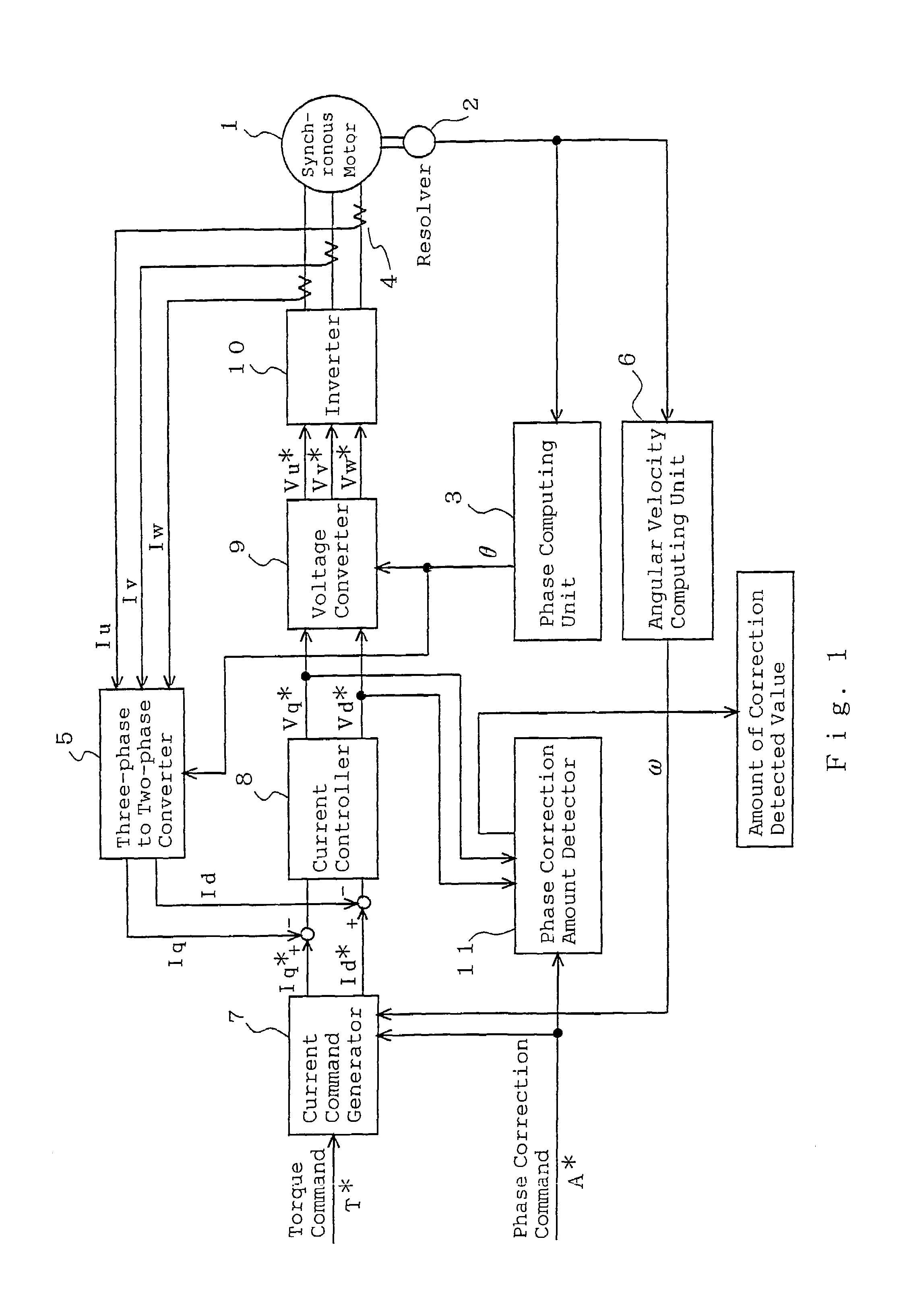
[0014]FIG. 1 is a block diagram of a motor apparatus for explaining an adjustment method of rotor position detection of a synchronous motor of Embodiment 1 according to the present invention. A synchronous motor apparatus includes a synchronous motor 1 having a permanent magnet field or winding field and a controller for controlling the synchronous motor 1. The controller includes a resolver 2, which is a rotational position detector, for detecting a rotor position of the synchronous motor 1; a phase computing unit 3 for computing a rotor position angle θ from an output of the resolver 2; a current detector 4 for detecting three-phase currents Iu, Iv, and Iw of the synchronous motor 1; and a three-phase to two-phase converter 5 for converting the rotor position angle θ and the three-phase currents Iu, Iv, and Iw to d-axis and q-axis currents (actual current).

[0015]Further, the controller includes an angular velocity computing unit 6 for determining the rotational angular velocity ω ...

embodiment 2

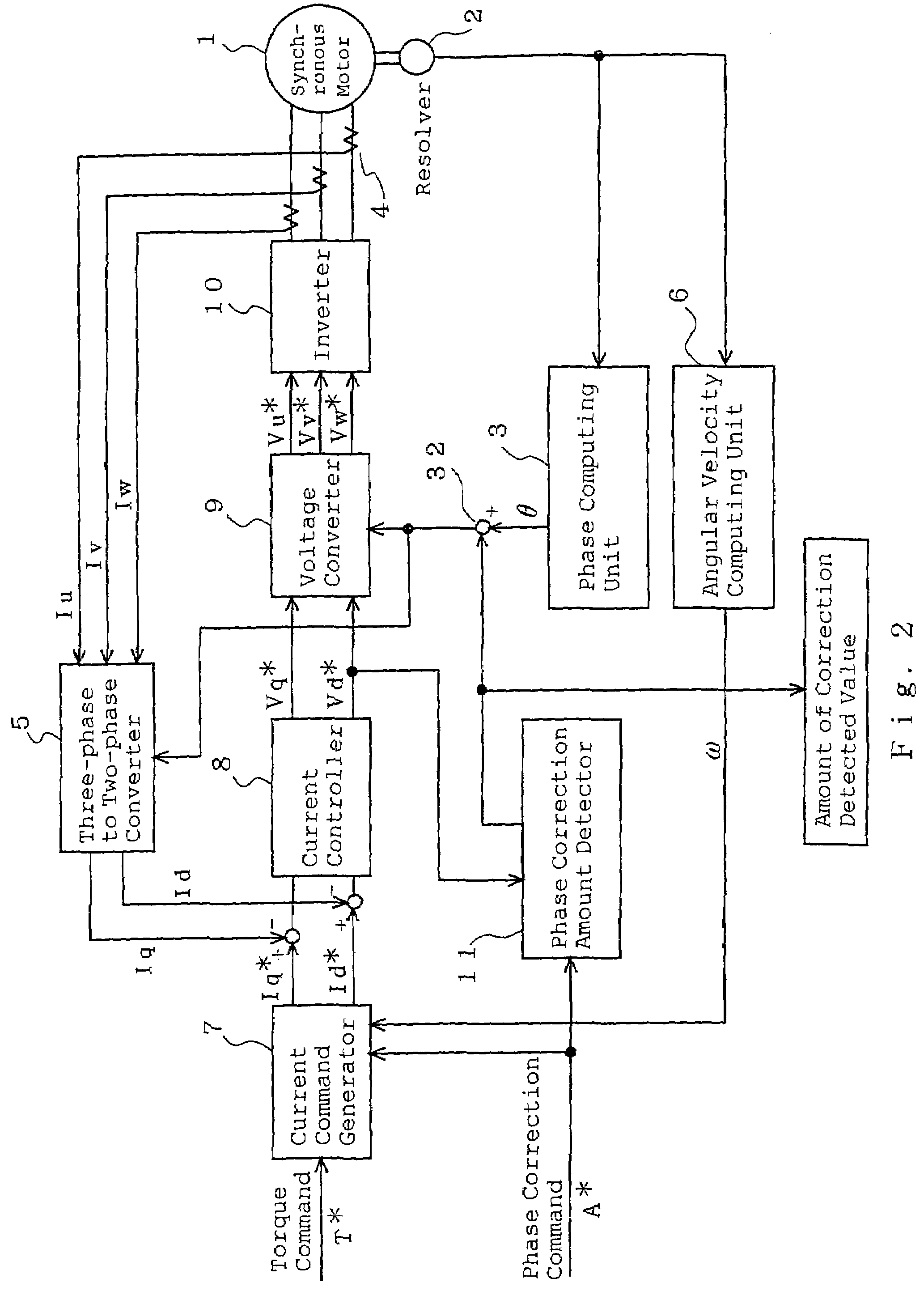
[0029]FIG. 2 is a block diagram for explaining an adjustment method of rotor position detection of a synchronous motor of Embodiment 2 according to the present invention. Referring to the drawings, the same reference numerals as those shown in FIG. 1 of Embodiment 1 represent the same or corresponding elements and elements different from FIG. 1 will be mainly described. A phase correction amount detector 11 inputs a d-axis voltage command Vd* to determine an amount of offset Δθ concerning a rotor position angle θ and outputs it to an adder 32 and also outputs it as an amount of correction detected value. The adder 32 adds the amount of offset Δθ to the rotor position angle θ of a phase computing unit 3.

[0030]A method of determining the amount of offset Δθ will be described. In Embodiment 1, the phase correction command for commanding adjustment for a rotational position deviation makes the d-axis current command and the q-axis current command zero regardless of the torque command an...

embodiment 3

[0036]Next, an adjustment method of mechanically shifting the position of a rotational position detector in a rotation direction will be described specifically. FIG. 3 is a longitudinal sectional view showing a synchronous motor of Embodiment 3 and FIG. 4 is a front view thereof. In the figures, a synchronous motor is composed of a rotor 12 wound by a field winding 12a, a stator 13 wound by three-phase stator windings 13a, a front bracket 14 and a rear bracket 15 holding the rotor 12 and the stator 13, a rotational position detector 16 for detecting a rotational state of the rotor 12, and the like. The rotor 12 is of a claw pole type.

[0037]The rotor 12 includes a rotational shaft 19 rotatably supported by the front bracket 14 and the rear bracket 15 via bearings 17 and 18 on both sides. One end portion of the rotational shaft 19 protrudes from the front bracket 14 and a pulley20 is fixed on its end portion. Further, two slip rings 21 are assembled on the other end portion of the rot...


PUM


Abstract

To obtain an adjustment method of rotor position detection of a synchronous motor with excellent productivity. An adjustment method of rotor position detection of a synchronous motor, wherein a synchronous motor having a stator wound around a stator coil and a rotor provided with magnetic poles, and a rotational position detector having a sensor rotor fixed to the rotor and a sensor stator disposed opposite to the sensor rotor for detecting a rotational position of the rotor are provided, and wherein an amount of deviation between the rotational position of the synchronous motor determined from an output of the rotational position detector and an actual rotational position of the synchronous motor is adjusted, the method comprising: a step of detecting the amount of deviation during rotation of the synchronous motor; and a step of mechanically adjusting a relative position between the rotational position detector and the synchronous motor based on a detected value of the amount of deviation, is provided.

Description

TECHNICAL FIELD[0001]The present invention relates to an adjustment method of rotor position detection of a synchronous motor and, more particularly, concerns a position adjustment method of a rotational position detector.BACKGROUND ART[0002]A conventional method of correcting a deviation generated between a rotational position of a synchronous motor determined from an output of a rotational position detector and an actual rotational position of the synchronous motor includes: a step of detecting a no-load state of the motor with a no-load detector; a step of detecting a motor voltage applied to a winding of the motor with a motor voltage detector; a step of computing d-axis and q-axis voltages from rotation angle information of the rotational position detector and the motor voltage; and a step of correcting the rotation angle so that the d-axis voltage becomes zero (see, for example, Patent Document 1).[0003]In the above described conventional method of correcting the deviation gen...

Claims


Application Information

Patent Timeline
Patent Type & Authority Patents(United States)
IPC IPC(8): H02P1/46H02P1/50H02P23/00H02P3/18H02P6/00H02K19/00H02K19/36H02P6/16H02P6/06H02P6/08H02P6/17H02P6/28H02P6/32H02P21/00H02P21/22H02P27/04
CPCH02K19/36H02P21/06
Inventor NISHIMURA, SHINJIUTSUMI, YOSHINOBUASAO, YOSHIHITO
Owner MITSUBISHI ELECTRIC CORP
Why Eureka
Try Eureka