Hydraulic control system for working machine

a control system and working machine technology, applied in the direction of fluid couplings, servomotors, couplings, etc., can solve the problems of inability to control the pump discharge quantity, the speed of the swing motor does not increase rapidly, and the energy efficiency is deteriorated, so as to reduce the flow rate and improve energy efficiency, no fear of acceleration performance and driving force impairmen

Active Publication Date: 2008-07-01
KOBELCO CONSTR MASCH CO LTD
View PDF13 Cites 40 Cited by
  • Summary
  • Abstract
  • Description
  • Claims
  • Application Information

AI Technical Summary

Benefits of technology

[0011]It is an object of the present invention to provide a hydraulic control system for a working machine which can decrease a relief loss and improve the energy efficiency while making the most of the ordinary control.
[0013]According to this configuration, the pump flow rate in the hydraulic pump is controlled on the basis of working information by the ordinary control means, the pump flow rate is controlled on the basis of the pump discharge pressure in the hydraulic pump by the pressure feedback control means, and the control wherein the pump flow rate becomes smaller than that of the other is selected out of the controls performed by both those control means, whereby the opening / closing control for the relief mechanism disposed on the discharge side of the hydraulic pump is performed. Thus, the pump discharge quantity can be controlled so as to be decreased by an amount matching the relief flow rate. Consequently, the relief flow rate decreases and so does the relief loss, whereby the energy efficiency is improved. Besides, since the pump discharge pressure is prevented from becoming too low, there is no fear of acceleration performance and driving force being impaired. In the present invention, moreover, the ordinary control is selected when the lever operation amount is made small and therefore the operability is not deteriorated.

Problems solved by technology

In this case, a large proportion of working oil fed from a hydraulic pump during operation of the relief valve is released directly to a tank through the relief valve without being fed to the hydraulic actuator, so that a large proportion of pump power is consumed as a loss of the relief valve, thus giving a rise to the problem that the energy efficiency is deteriorated.
However, for example in the case where a hydraulic actuator is a swing motor, the speed of the swing motor does not increase rapidly under the influence of inertia of a swing body.
However, according to the technique disclosed in Patent Document 1 it is impossible to control the pump discharge quantity so as to decrease by an amount matching the relief flow rate.
Therefore, if the decrease quantity of the pump discharge quantity is smaller than the amount matching the relief flow rate, the pump discharge pressure exceeds the relief pressure, causing operation of the relief valve, with consequent creation of a large relief flow rate posing the problem that the energy efficiency is deteriorated.
If the decrease quantity of the pump discharge pressure is larger than the amount matching the relief flow rate, the relief valve fails to operate and there also arises the problem that the accelerating ability is impaired due to an excessive lowering of the pump discharge pressure.
According to the technique disclosed in Patent Document 2, there occurs a pressure loss due to the throttle provided on the downstream side of the relief valve and hence it is impossible to improve the energy efficiency.
According to the technique disclosed in Patent Document 3, heat capacity of the relief valve causes a very large time lag between the creation of relief flow rate and the rise in temperature of the relief valve, so that an excessive time delay occurs from the time when relief flow is created to cut-off of pump flow rate, and thus the relief loss is not fully diminished.
Even after the arrival of relief flow rate at zero, the pump flow is cut off for the detection of remaining heat and it becomes impossible to obtain a required driving force.
As a result, a differential pressure in a meter-in circuit becomes very high, producing an extremely heavy meter-in loss, whereby the operability is deteriorated.

Method used


Image

  • Hydraulic control system for working machine
  • Hydraulic control system for working machine
  • Hydraulic control system for working machine

Examples


first embodiment

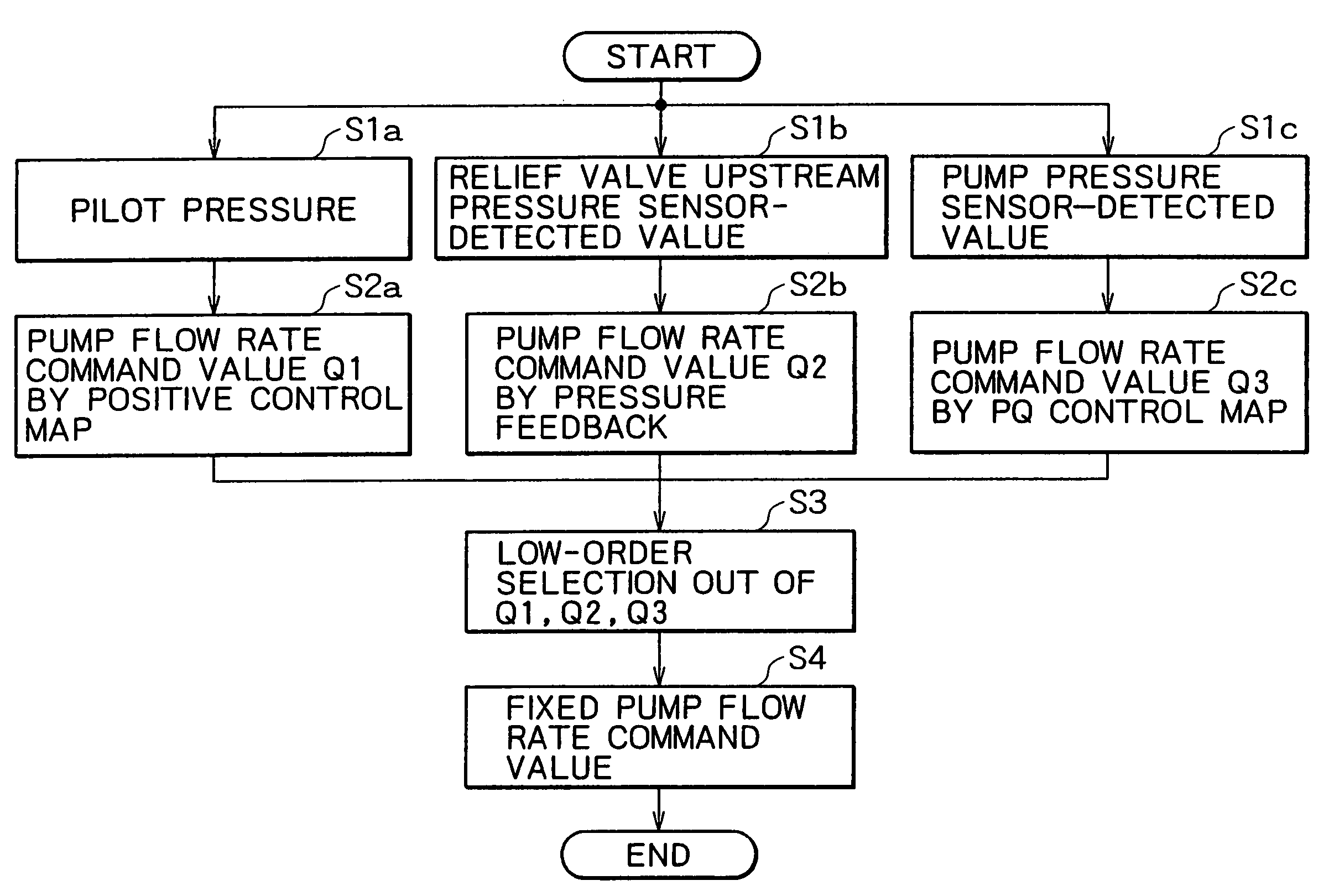
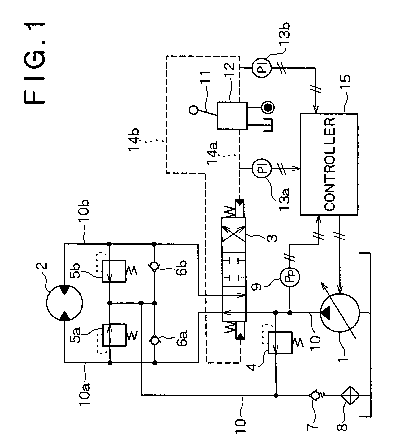
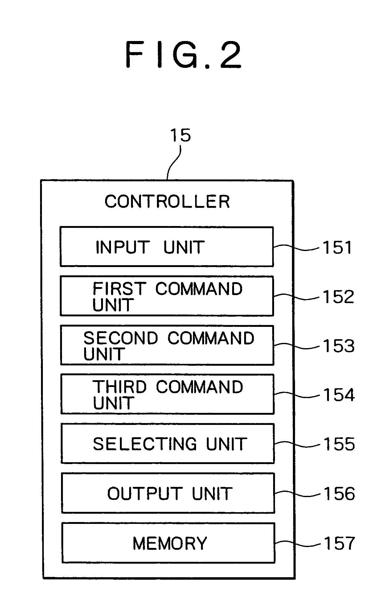
[0028]FIG. 1 illustrates a hydraulic control system for a working machine according to a first embodiment of the present invention and FIG. 2 is a block diagram of a controller.

[0029]In FIG. 1, numeral 1 denotes a variable capacity type hydraulic pump, numeral 2 denotes a hydraulic motor as an example of a hydraulic actuator, numeral 3 denotes a control valve for controlling the supply and discharge of working oil to and from the hydraulic motor 2, numeral 4 denotes a main relief valve as an example of a relief mechanism, numerals 5a and 5b denote port relief valves, numerals 6a and 6b denote check valves for make-up, numeral 7 denotes a back pressure check valve, numeral 8 denotes an oil cooler, and numeral 9 denotes a pressure sensor. All of these elements are connected to a main line 10 (10a, 10b). Numeral 11 denotes an operating lever, numeral 12 denotes a remote control valve for generating a pilot pressure in pilot lines 14a and 14b in accordance with a lever operation amount,...

second embodiment

[0054]FIG. 9 illustrates a hydraulic control system for a working machine according to a second embodiment of the present invention and FIG. 10 is an explanatory diagram showing a pressure-flow rate response relation in the port relief valves. In this second embodiment, elements common to the first embodiment are identified by the same reference numerals as in the first embodiment and tautological explanations thereof will be omitted.

[0055]In the hydraulic control system of this second embodiment, as shown in FIG. 9, pilot lines 14a and 14b are branched to provide pilot lines 14c and 14d communicating with spring chambers of the port relief valves 5a and 5b. The operation of this system configuration will be described below.

[0056]FIG. 9 shows a state in which a pilot pressure is developed on the pilot line 14a by operation of the operating lever 11, and with the control valve 3 switched to the right side, the main line 10a becomes a working oil supply side and the main line 10b beco...

third embodiment

[0063]FIG. 11 is an explanatory diagram showing a control method using mode switching.

[0064]In a controller 15 according to this third embodiment, it is possible to make an ON / OFF selection in the pressure feedback control by the first command unit 152. As shown in FIG. 11, the controller 15 includes an energy saving mode processing unit 302 for the execution of processing in an energy saving mode (first mode), a high power mode processing unit 303 for the execution of processing in a high power mode (second mode), and a mode select switch 301 for switching a mode to the other mode. Other elements are the same as in the first and second embodiments.

[0065]The energy saving mode processing unit 302, upon receipt of a switching signal from the mode select switch 301, provides a command signal for ON selection of the pressure feedback control to the first command unit 152.

[0066]The high power mode processing unit 303, upon receipt of a switching signal from the mode select switch 301, p...


PUM


Abstract

A hydraulic control system for a working machine according to the present invention comprises a hydraulic pump for supplying working oil to a hydraulic actuator through a control valve, a relief mechanism disposed on the discharge side of the pump, the relief mechanism assuming an open state when a pump discharge pressure which varies according to the pump flow rate exceeds a predetermined pressure and assuming a closed state when the pump discharge pressure becomes the predetermined one or lower, an ordinary control means for controlling the pump flow rate in accordance with working information, and a pressure feedback control means for controlling the pump flow rate in accordance with the pump discharge pressure. In this system, out of controls performed by both control means, control wherein the flow rate by one control becomes smaller than that of the other is selected, thereby opening / closing control of the relief mechanism is performed. According to this, it is possible to decrease the relief loss and improve the energy efficiency while making the most of the ordinary control.

Description

BACKGROUND OF THE INVENTION[0001]1. Field of the Invention[0002]The present invention relates to a hydraulic control system for a working machine such as a hydraulic excavator.[0003]2. Description of the Related Art[0004]According to a conventional hydraulic system in a working machine, when a large load is imposed on a hydraulic actuator with a consequent increase in internal pressure of the hydraulic system, working oil is released to a tank through a relief valve to prevent an excessive increase of pressure and thereby prevent a damage to hydraulic devices.[0005]In this case, a large proportion of working oil fed from a hydraulic pump during operation of the relief valve is released directly to a tank through the relief valve without being fed to the hydraulic actuator, so that a large proportion of pump power is consumed as a loss of the relief valve, thus giving a rise to the problem that the energy efficiency is deteriorated.[0006]For example, FIGS. 13A to 13D are explanatory ...

Claims


Application Information

Patent Timeline
Patent Type & Authority Patents(United States)
IPC IPC(8): F16D31/02E02F9/22F15B11/00F15B11/042F15B11/16F15B21/08
CPCF15B11/0423F16H61/431F15B21/082F15B21/087F16H61/4017F16H61/4061F16H61/4148F15B11/167F15B2211/20546F15B2211/255F15B2211/3052F15B2211/3111F15B2211/329F15B2211/50518F15B2211/50536F15B2211/50545F15B2211/5151F15B2211/5153F15B2211/528F15B2211/55F15B2211/62F15B2211/6316F15B2211/6652F15B2211/7058F16H2059/6861
Inventor SUGANO, NAOKI
Owner KOBELCO CONSTR MASCH CO LTD
Why Eureka
Try Eureka