Computerized tomography (CT) imaging system with monoblock X-ray tube assembly

a computerized tomography and monoblock technology, applied in the field of anatomical imaging systems, can solve the problems of tissue oxygen deprivation, tissue damage, and the effectiveness of a particular treatment may be time-sensitive, and achieve the effect of facilitating a reduction in the size, weight and cost of the ct scanner

Active Publication Date: 2008-07-08
NEUROLOGICA CORP
View PDF13 Cites 14 Cited by
  • Summary
  • Abstract
  • Description
  • Claims
  • Application Information

AI Technical Summary

Benefits of technology

[0012]In accordance with the present invention, there is provided a novel system for cooling the X-ray tube in a CT scanner, wherein the novel system facilitates a reduction in the size, weight and cost of the CT scanner.
[0013]And there is provided a novel X-ray tube assembly for use in a CT scanner, wherein the novel X-ray tube assembly comprises an X-ray tube and its associated cooling system, and further wherein the novel X-ray tube assembly is relatively compact, lightweight and inexpensive.
[0014]And there is provided a novel CT machine incorporating the novel X-ray tube assembly, wherein the novel CT machine is relatively small, mobile and inexpensive.

Problems solved by technology

Strokes are caused by an abrupt interruption of the blood supply to the brain or spinal cord, thereby depriving the tissue of oxygen and resulting in tissue damage.
This is because the treatment for an ischemic stroke may be contra-indicated for the treatment for a hemorrhagic stroke and, furthermore, the effectiveness of a particular treatment may be time-sensitive.
However, current diagnosis times, i.e., the time needed to identify that the patient is suffering from a stroke and to identify the hemorrhagic or ischemic nature of the stroke, frequently exceeds this 3 hour window.
Unfortunately, in practice, the CT machine is typically located in the hospital's radiology department and the patient is typically received in the hospital's emergency room, and the “round-trip” time between the emergency room and the radiology department can frequently involve substantial delays, even in the best of hospitals.
As a result, the time spent in transporting the patient from the emergency room to the radiology department and then back again can consume critical time which can compromise proper treatment of the patient.
However, it can be troublesome to dissipate this heat, particularly inasmuch as the X-ray tube: (i) is encapsulated by the scanner housing, which tends to trap the heat from the X-ray tube; (ii) is generally in close proximity to many other internal scanner components, which can also trap heat; and (iii) must keep at least the emitter portion of the X-ray tube exposed, in order to permit the X-rays to exit the tube and pass into the patient.
Such considerations have generally resulted in relatively complex X-ray tube assemblies comprising the X-ray tube and its associated cooling system, which can add to scanner size, weight and cost.
This is particularly true inasmuch as the X-ray tubes (and hence their associated cooling systems) are generally mounted on large rotating drums which move the X-ray tubes concentrically about the patient so as to achieve the necessary scanning angles; such rotational mounting generally complicates the delivery of power and / or fluids to the X-ray tube's cooling system.

Method used


Image

  • Computerized tomography (CT) imaging system with monoblock X-ray tube assembly
  • Computerized tomography (CT) imaging system with monoblock X-ray tube assembly
  • Computerized tomography (CT) imaging system with monoblock X-ray tube assembly

Examples


Embodiment Construction

CT Machine 5 In General

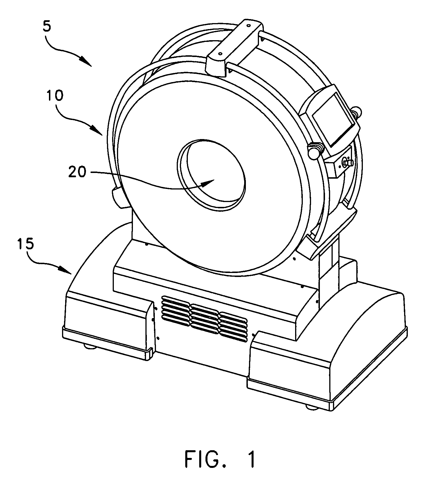
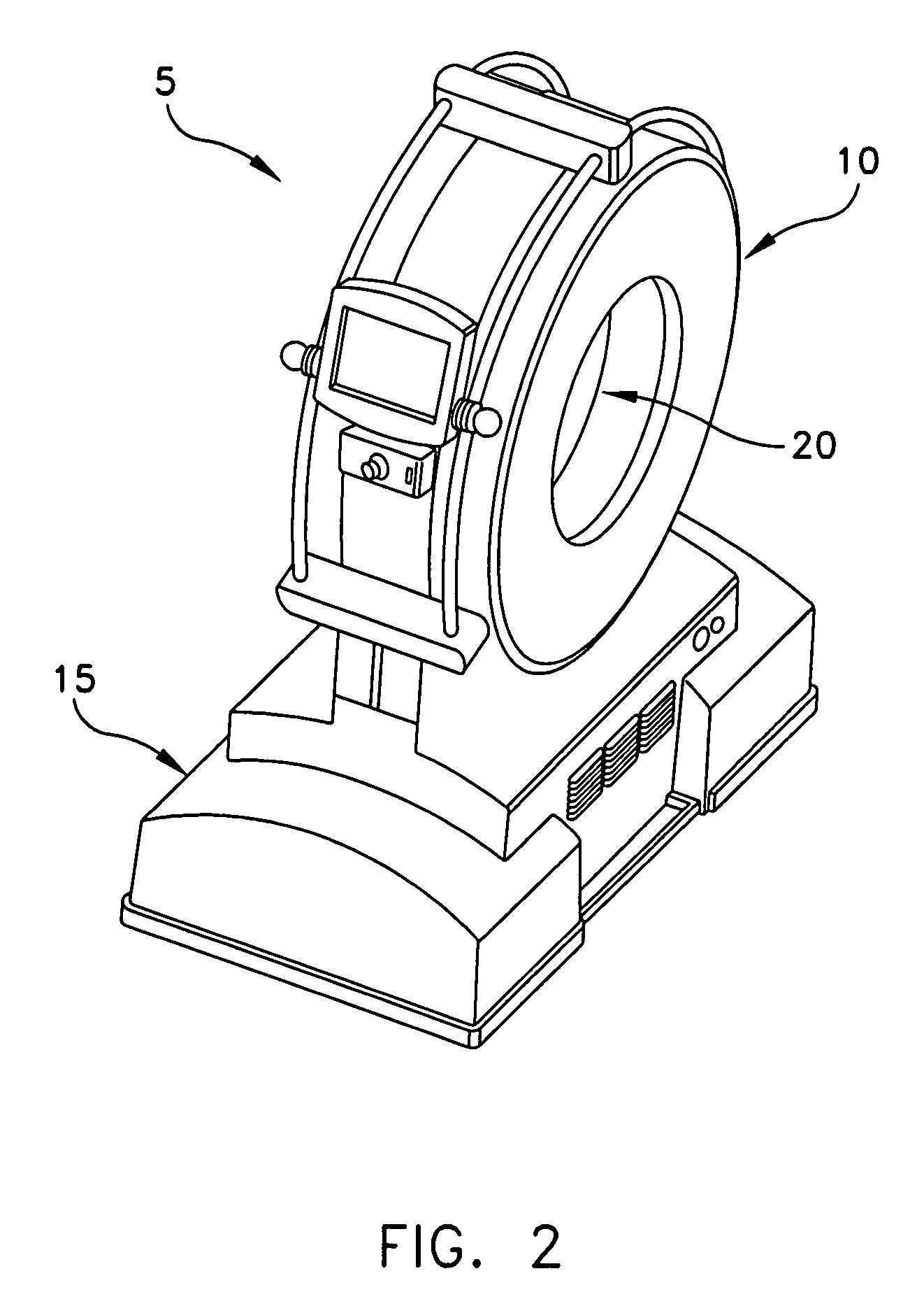
[0055]Looking first at FIGS. 1 and 2, there is shown a novel CT machine 5 formed in accordance with the present invention. CT machine 5 generally comprises a torus 10 which is supported by a base 15. A center opening 20 is formed in torus 10. Center opening 20 receives the patient anatomy which is to be scanned, i.e., the head of the patient when CT machine 5 is to be used in stroke applications.

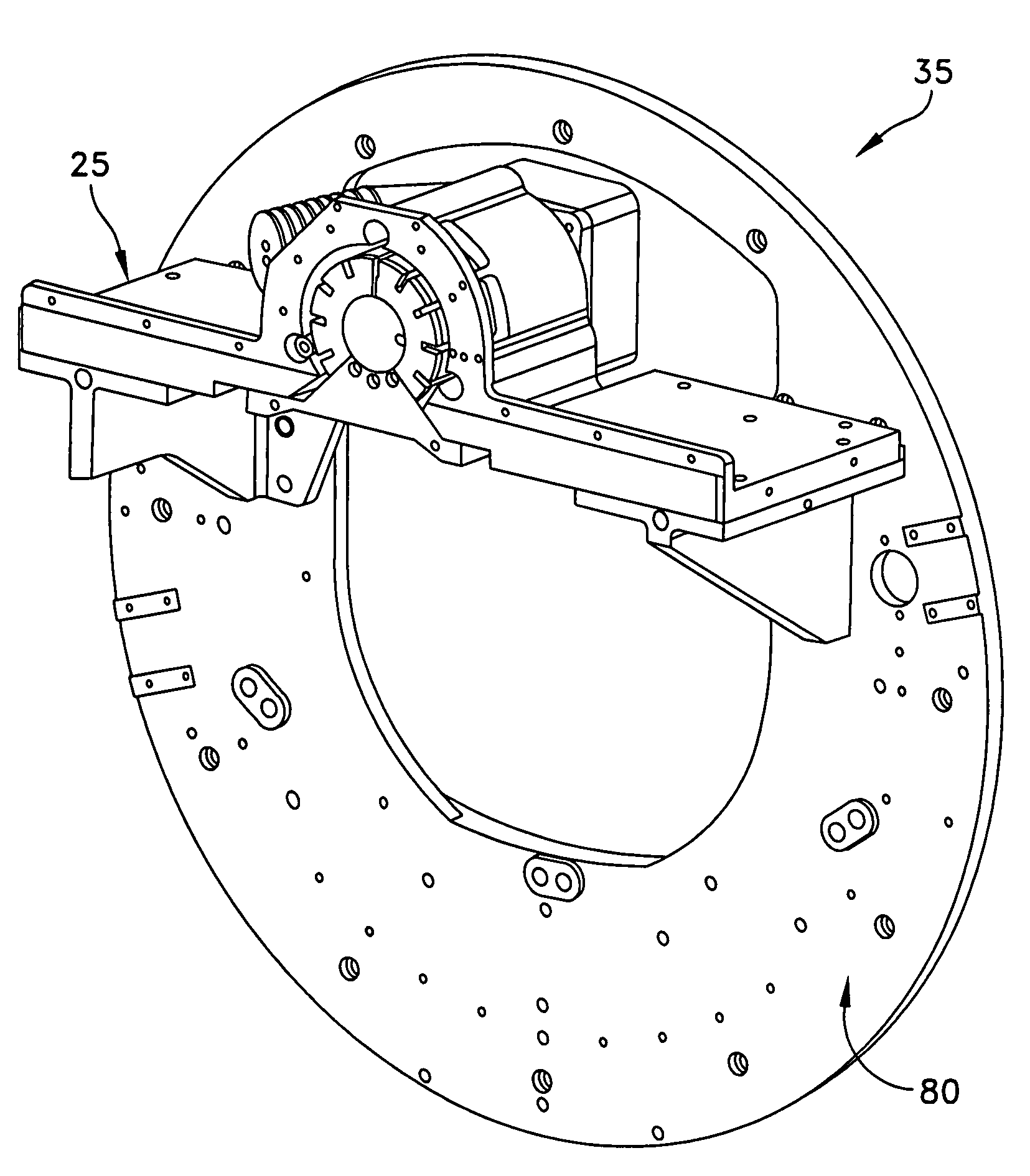
[0056]Looking next at FIG. 3, torus 10 generally comprises a X-ray tube assembly 25, an X-ray detector assembly 30, and a rotating drum assembly 35. X-ray tube assembly 25 and X-ray detector assembly 30 are mounted to the rotating drum assembly 35 in diametrically-opposing relation, such that the X-ray beam 40 (generated by X-ray tube assembly 25 and detected by X-ray detector assembly 30) is passed through the patient anatomy disposed in center opening 20. Furthermore, since X-ray tube assembly 25 and X-ray detector assembly 30 are mounted on the rotating drum assembl...


PUM


Abstract

A system for cooling an X-ray tube in a CT machine comprising a heat sink for drawing heat away from the X-ray tube and a collimator connected to the heat sink and adapted to collimate the X-rays emitted by the X-ray tube and “focus” those X-rays on an X-ray detector, the heat sink body being formed out of the same material as the emitter of the X-ray tube, such that the emitter opening of the X-ray tube will remain aligned with both the heat sink window and the collimator opening even when the emitter of the X-ray tube undergoes thermal expansion.

Description

REFERENCE TO PENDING PRIOR PATENT APPLICATION[0001]This patent application is a continuation-in-part of prior U.S. patent application Ser. No. 11 / 193,941, filed Jul. 29, 2005 now U.S. Pat. No. 7,175,347 by Andrew P. Tybinkowski et al. for ANATOMICAL IMAGING SYSTEM WITH CENTIPEDE DRIVE, which patent application in turn claims benefit of: (i) prior U.S. Provisional Patent Application Ser. No. 60 / 670,164, filed Apr. 11, 2005 by Andrew P. Tybinkowski et al. for ANATOMICAL IMAGING SYSTEM WITH CENTIPEDE DRIVE; and (ii) prior U.S. Provisional Patent Application Ser. No. 60 / 593,001, filed Jul. 30, 2004 by Bernard Gordon et al. for ANATOMICAL SCANNING SYSTEM.[0002]The three above-identified patent applications are hereby incorporated herein by reference.FIELD OF THE INVENTION[0003]This invention relates to anatomical imaging systems in general, and more particularly to Computerized Tomography (CT) imaging systems.BACKGROUND OF THE INVENTION[0004]Strokes are the third leading cause of death i...

Claims


Application Information

Patent Timeline
Patent Type & Authority Patents(United States)
IPC IPC(8): H01J35/12G21K1/02
CPCA61B6/032A61B6/04A61B6/4488G21K1/02H05G1/025G01N2223/612H01J2235/125H01J2235/1291G01N2223/419H01J2235/1216
Inventor TYBINKOWSKI, ANDREW P.NEMIROVSKY, LIDIABAILEY, ERIC M.
Owner NEUROLOGICA CORP
Why Eureka
Try Eureka