Raman spectrometer

a raman spectrometer and scatter light technology, applied in the field of spectroscopy, can solve the problems of reducing or adversely affecting the precision and affecting the accuracy of raman scatter light measurements, and not always achieving uniform, predictable results

Active Publication Date: 2008-07-22
SCIAPS +2
View PDF14 Cites 42 Cited by
  • Summary
  • Abstract
  • Description
  • Claims
  • Application Information

AI Technical Summary

Problems solved by technology

While these principles and phenomena are known, until recently efforts to apply the principles and phenomena to qualitative and quantitative analyses of samples have not always resulted in uniform, predictable results, or in acceptable levels of precision and accuracy of Raman spectra.
Because of instrumentation variabilities, inherent weakness of a Raman scattered signal, fluorescence, and other limitations associated with spectroscopy instruments, the goal of producing a standard Raman spectrum for use in sample analyses was, until recently, a challenge not achieved by apparatus and methods known in the art.
At least one problem that had to be overcome was the fact that spectroscopic measurements of Raman scattered light seeking to measure wavelength or intensities, or both, of scattered light, could be affected by the instrument, or spectroscopic system, itself.
Any one, or all, of such components of a conventional spectrometer system induced or contributed to instrumentation variabilities that reduced or adversely affected the precision and accuracy of measurements of Raman scattered light.
Use of semiconductor or diode lasers, while useful because of a number of important characteristics, also engender unique problems that, if solved, would advance Raman technology.
However, at least one other problem associated with semiconductor diode lasers is the tendency for the output to change from one frequency to another during operation, commonly referred to as frequency drift.
Semiconductor diode lasers also are susceptible to mode hops when the laser switches output from one frequency to a new preferred frequency.
All of those solutions are achieved at considerable expense, and generally shorten the useful life of a semiconductor laser.
A further problem related to diode lasers includes variations in output intensity that directly affect the measured Raman shift.
The '971 patent, however, requires monitoring the laser output frequency and performing complex integration routines to obtain a Raman spectrum for a sample.
A further complication arises from multiple lines in the frequency of the source of incident radiation that may cause shifted, multiple sets of spectra from a sample.
An undesirable result of incident radiation on a sample occurs if a sample generates red shifted radiation as part of a radiation absorption process, a phenomenon commonly referred to as fluorescence.
Fluorescence is a major interference for samples using excitation wavelengths in the visible region of the light spectrum, and has therefore made use of blue and green excitation sources problematic.
Using excitation sources in the far end of the red end of the light spectrum mitigates the fluorescence effect, however, particularly in connection with silicon detectors, but substantially restricts use of instrument components that tend to provide radiation far into the infrared (“IR”) region of the light spectrum.

Method used


Image

  • Raman spectrometer
  • Raman spectrometer
  • Raman spectrometer

Examples


Embodiment Construction

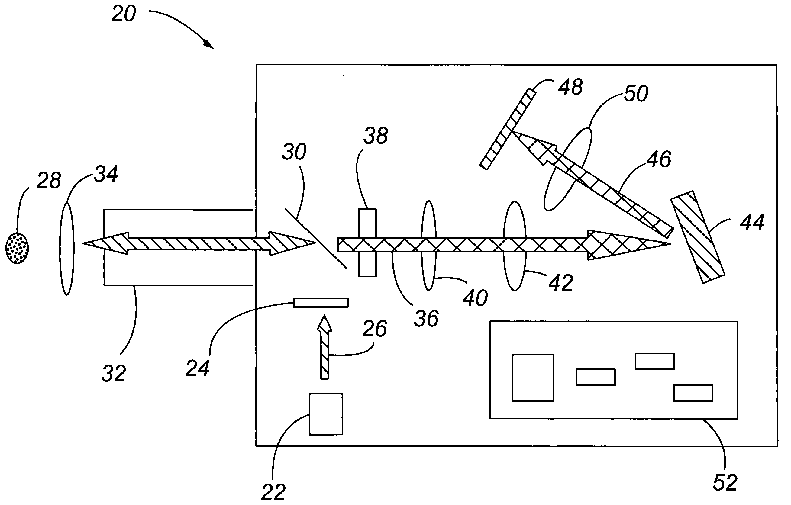
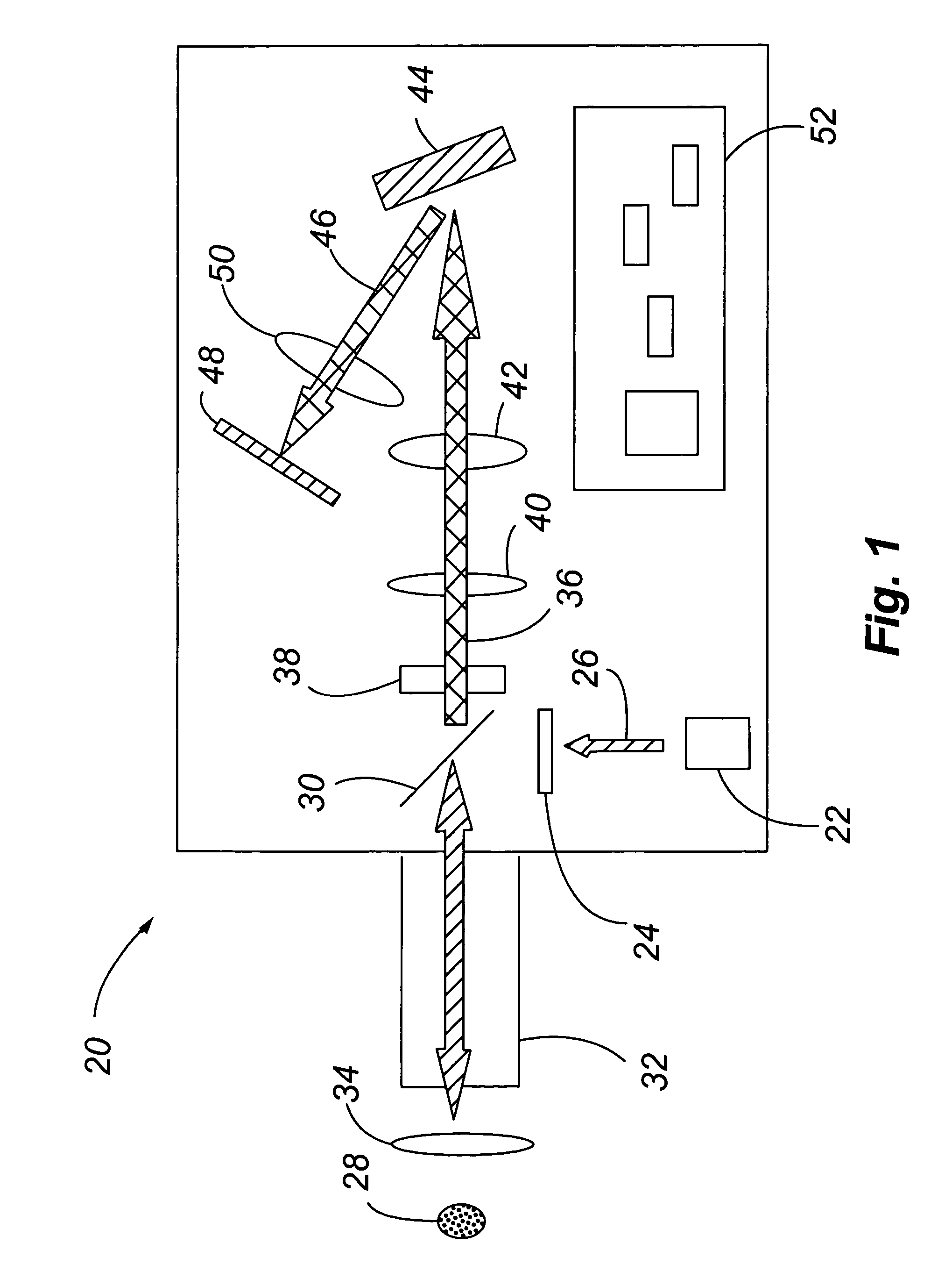
[0048]FIG. 1 shows one embodiment of a Raman spectrometer 20 according to the present invention. As shown in FIG. 1, the Raman spectrometer comprises an excitation source 22. The excitation source 22 typically comprises a laser light source. In one embodiment, for example, the excitation source 22 comprises a diode laser. A diode laser, for example, is capable of providing a plurality of wavelengths from the excitation source 22. The spectrometer 20 further comprises a filter 24. The filter 24 filters the output of the excitation source 22, such as removing spurious emissions from the excitation source 22.

[0049]The spectrometer 20 further comprises a means for directing the incident beam 26 toward a sample 28. In the embodiment shown in FIG. 1, for example, the means for directing the incident beam 26 toward the sample 28 comprises a dichroic beam-splitter mirror 30. However, the incident beam 26 may be directed at sample 28 without any intervening instrument components being locate...


PUM

PropertyMeasurementUnit
diameteraaaaaaaaaa
diameteraaaaaaaaaa
Raman spectrumaaaaaaaaaa

Abstract

A system, method and apparatus for taking a Raman spectrum of a sample is disclosed. In one embodiment, for example, an integrated Raman spectrometer is provided. In another embodiment, a portable Raman spectrometer is provided. In another embodiment, a Raman spectrometer is provided comprising a collimated beam tube for transmitting excitation radiation to an external optical system, such as a microscope, a telescope or a camera lens. In another embodiment, a method for correcting a Raman spectrum for background interference is provided. In yet another embodiment, a method for rejecting fluorescence in a Raman spectrometer is provided. A chemical reactor comprising a built-in Raman detector for monitoring a chemical reaction in a reaction chamber of the reactor is also provided.

Description

CROSS-REFERENCE TO RELATED APPLICATIONS[0001]The present application claims the benefit of U.S. Provisional Patent Application Ser. No. 60 / 568,895 entitled “Raman Spectrometer” and filed by Keith T. Carron et al. on May 7, 2004, which is incorporated into this application in its entirety.STATEMENT REGARDING FEDERALLY SPONSORED RESEARCH OR DEVELOPMENT[0002]This invention was made with Government support under Contract No. R44 DA13055 awarded by the National Institutes of Health. The Government has certain rights in this invention.FIELD OF THE INVENTION[0003]The present invention is generally related to the field of spectroscopy, and more particularly to a system, method and apparatus for adjusting spectral measurements to achieve a Raman spectrum.BACKGROUND OF THE INVENTION[0004]Spectroscopy is a general term for the process of measuring energy or intensity as a function of wavelength in a beam of light or radiation. Many conventional spectrometers, and components comprising a spect...

Claims


Application Information

Patent Timeline
Patent Type & Authority Patents(United States)
IPC IPC(8): G01J3/44G01N21/65
CPCG01J3/02G01J3/0272G01J3/0291G01N21/65G01J3/44G01N2201/0813G01N2201/0221G01N2201/0612G01J2003/4424
Inventor CARRON, KEITH T.WATSON, MARK A.BULLER, SHANE A.
Owner SCIAPS
Why Eureka
Try Eureka