
Optical fiber with extended bandwidth for crimp and cleave connectors

a technology of optical fiber and connector, which is applied in the direction of glass optical fiber, cladded optical fibre, instruments, etc., can solve the problems of difficult to use such optical fiber in newer applications, high speed or longer fiber link lengths, and reduce the service life of optical fiber, so as to increase the bandwidth-length product of optical fiber, the effect of high bandwidth connectorization

Active Publication Date: 2008-07-29
FURAKAWA ELECTRIC NORTH AMERICA INC
View PDF19 Cites 3 Cited by
  • Summary
  • Abstract
  • Description
  • Claims
  • Application Information

AI Technical Summary

Benefits of technology

"The patent describes a special optical fiber that has a high bandwidth and is easy to connect. The fiber has a core and a cladding layer, with the core having a higher refractive index than the cladding layer. A coating layer is also included to further increase the bandwidth. The coating layer is made of a polymer that has good adhesion to the fiber and is durable enough for connectorization. The technical effect of this design is that it allows for high-speed data transmission and easy connection to optical devices."

Problems solved by technology

Such methods have been successful in the past, but are relatively complex, time consuming and expensive.
However, because of its low bandwidth-length-product (BLP), approximately 10 MHz-km., it is difficult to use such optical fiber in newer applications which may require higher speeds or longer fiber link lengths.
Increasing the refractive index of silica is accomplished by the addition of Germanium (Ge) or other known refractive increasing elements to the silica but is expensive in such large core fibers.
However, with the large silica cores of the prior optical fibers used in crimp and cleave connectors, the addition of Ge to the entire core is prohibitive because of its cost and will not yield a sufficient increase in BLP for the fiber.

Method used


Image

  • Optical fiber with extended bandwidth for crimp and cleave connectors
  • Optical fiber with extended bandwidth for crimp and cleave connectors
  • Optical fiber with extended bandwidth for crimp and cleave connectors

Examples


example 1

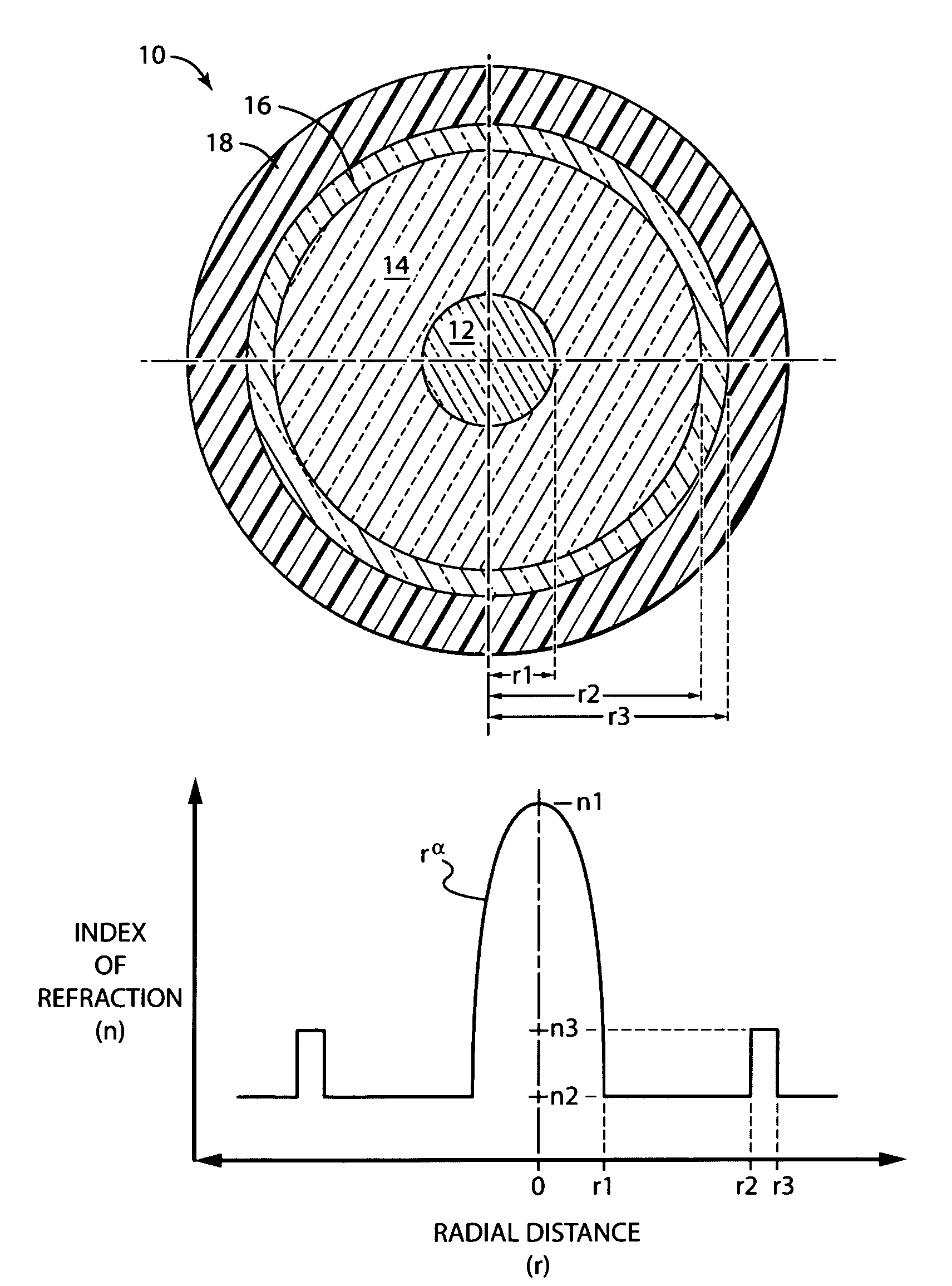
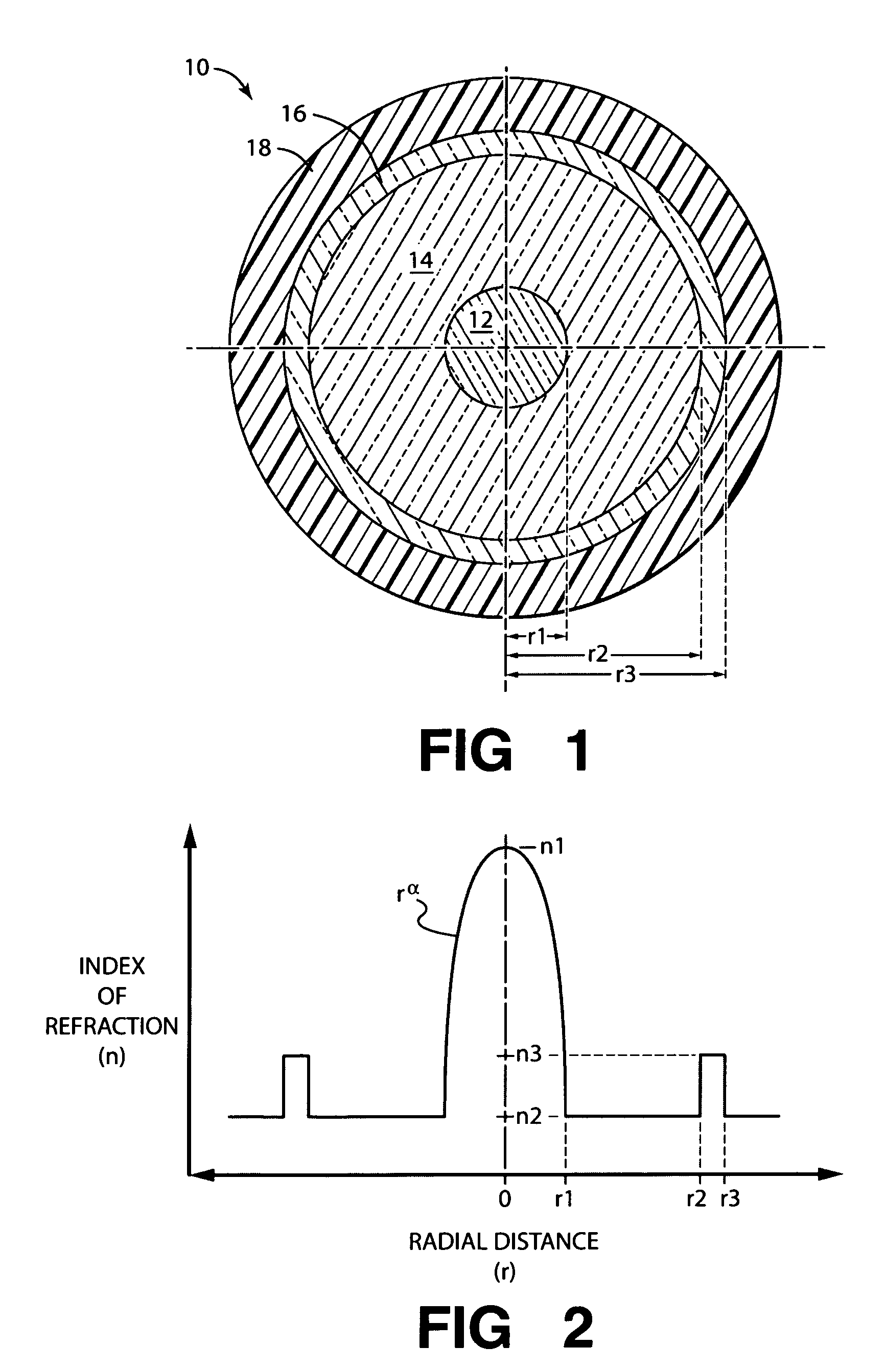
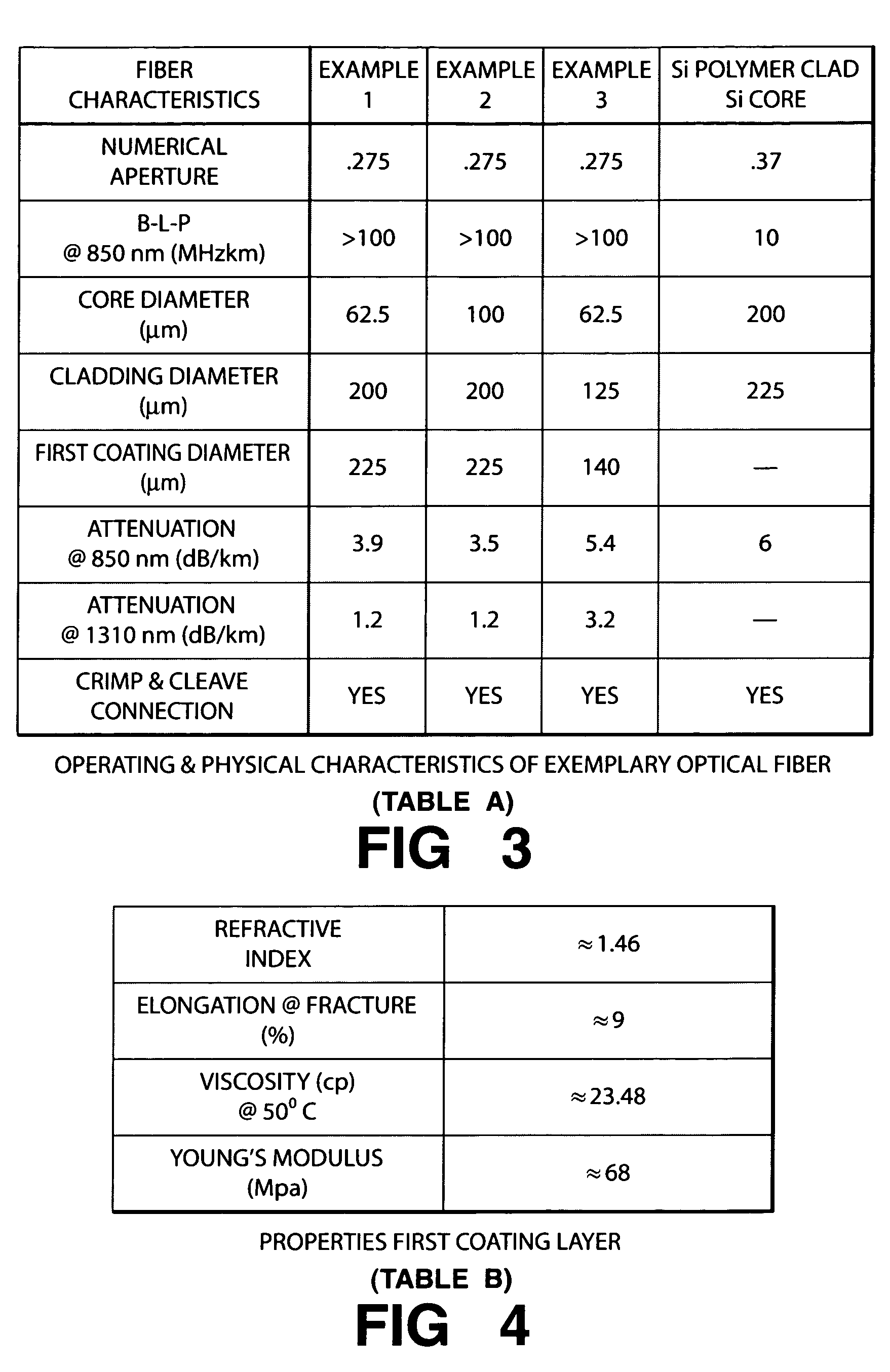
[0026]A preform manufactured by an MCVD process to provide a Ge doped core and a non-doped silica cladding. The optical profile of the preform is such that, when it is drawn, the optical fiber produced will have a core diameter of 62.5 μm and a clad diameter of 200 μm. The refractive index of the core is a graded profile and varies as a power function of the radial distance from the center of the fiber, Rα, where α=˜2. The refractive index of the cladding is approximately that of silica. The preform was then set on a draw tower with one end in a furnace. When the draw or drip end of the preform became molten it was tensioned and optical fiber was drawn from it. During drawing, the optical fiber is first coated with a UV curable polymer formulated according to Skutnik, et al. to have the properties of set forth in Table B of FIG. 4 by the application of a uniform and thin layer of liquid polymer via a coating die. The first coating was applied to a thickness of ˜12 μm. and has a refr...

example 2

[0028]A preform manufactured by an MCVD process to provide a Ge doped core and a non-doped silica cladding. The optical profile of the preform is such that, when it is drawn, the optical fiber produced will have a core diameter of 100 μm and a clad diameter of 200 μm. The refractive index of the core is a graded profile and varies as a power function of the radial distance from the center of the fiber, Rα, where α=˜2. The refractive index of the cladding is approximately that of silica. The preform was then set on a draw tower with one end in a furnace. When the draw or drip end of the preform became molten it was tensioned and optical fiber was drawn from it. During drawing, the optical fiber is first coated with a UV curable polymer formulated according to Skutnik, et al. to have the properties of set forth in Table B of FIG. 4 by the application of a uniform and thin layer of liquid polymer via a coating die. The first coating was applied to a thickness of ˜12 μm. and has a refra...

example 3

[0030]A preform manufactured by an MCVD process to provide a Ge doped core and a non-doped silica cladding. The optical profile of the preform is such that, when it is drawn, the optical fiber produced will have a core diameter of 62.5 μm and a clad diameter of 125 μm. The refractive index of the core is a graded profile and varies as a power function of the radial distance from the center of the fiber, Rα, where α=˜2. The refractive index of the cladding is approximately that of silica. The preform was then set on a draw tower with one end in a furnace. When the draw or drip end of the preform became molten it was tensioned and optical fiber was drawn from it. During drawing, the optical fiber is first coated with a UV curable polymer formulated according to Skutnik, et al. to have the properties of set forth in Table B of FIG. 4 by the application of a uniform and thin layer of liquid polymer via a coating die. The first coating was applied to a thickness of ˜12 μm. and has a refr...


PUM

PropertyMeasurementUnit
diameteraaaaaaaaaa
diameteraaaaaaaaaa
refractive indexaaaaaaaaaa

Abstract

An optical fiber includes a large graded index core of Ge doped silica for an increased bandwidth-length-product of over 100 MHz-km. A cladding layer of non-doped silica is formed on the core during the preform process and subsequently during drawing the preform an ultraviolet light curable polymer first coating is overlaid on the cladding layer. The first coating is sufficiently hardened to match the fracture characteristics of the silica core and cladding layer to facilitate crimp and cleave termination. The first coating is additionally provided with an index of refraction greater than the cladding layer to enable mode or energy stripping from the cladding layer. A second polymer layer may optionally be applied during draw for protection and to provide a tough outer layer of the optical fiber for the deformable features of a connector to hold onto after crimping.

Description

BACKGROUND OF THE INVENTION[0001]1. Field of the Invention[0002]The invention pertains generally to optical fibers with high bandwidth and low attenuation and is more particularly directed to such optical fibers which can be easily terminated with a simple crimp and cleave connector process.[0003]2. Description of Related Art[0004]Optical fiber has revolutionized the communications industry in providing a low cost high bandwidth transmission medium for all types and forms of information. An area in optical fiber communications systems where improvements are continuing to be made is in the connectorization of such fibers. Because the optical fibers of these systems are essentially made of a silica glass and the diameters of the fiber are small, it is essential to put a connector on the ends of the fiber for the purpose of joining two pieces of fiber together or plugging the fiber into optical transmitter and receiver. Connectors can be put on the fiber by fusion splicing the fiber to...

Claims


Application Information

Patent Timeline
Patent Type & Authority Patents(United States)
IPC IPC(8): G02B6/02
CPCG02B6/0288G02B6/02395G02B6/03644G02B6/03627C03B2203/26G02B6/14Y02P40/57
Inventor HOKANSSON, ADAM S.LI, JIESUN, XIAOGUANG
Owner FURAKAWA ELECTRIC NORTH AMERICA INC
Learn More