[0023]In accordance with one aspect of the invention, an optimized water profile within the fuel cell is achieved by using water management elements to confine a substantial portion of the water of the fuel cell between the two
diffusion layers, minimizing water loss or
discharge from the fuel cell. This is accomplished using a water management component such as a hydrophobic microporous layer, or a water management film placed in intimate contact with the
cathode catalyst, or with both
anode and
cathode catalyst layers, and applying sufficient compression to maintain effective uniform adhesion of such water management component to the catalyst layer even as
liquid water builds up at the interface between the catalyst layer and said water management component, thus ensuring water back-flow from the cathode into the membrane.
[0025]Consequently, a net flow of water from anode to cathode typically occurs as current is generated by the fuel cell. Therefore, in order to maintain optimal water distribution between cell anode and cell cathode, as required for sufficient water availability for the anodic process and in order to keep the
Nafion® membrane well hydrated, typical Class A DMFC systems collect water from the cathode and actively return it to the anode externally to the fuel cell via recirculation and pumping subsystems. As noted, these pumps can complicate the
system, increase its volume and result in parasitic power losses.
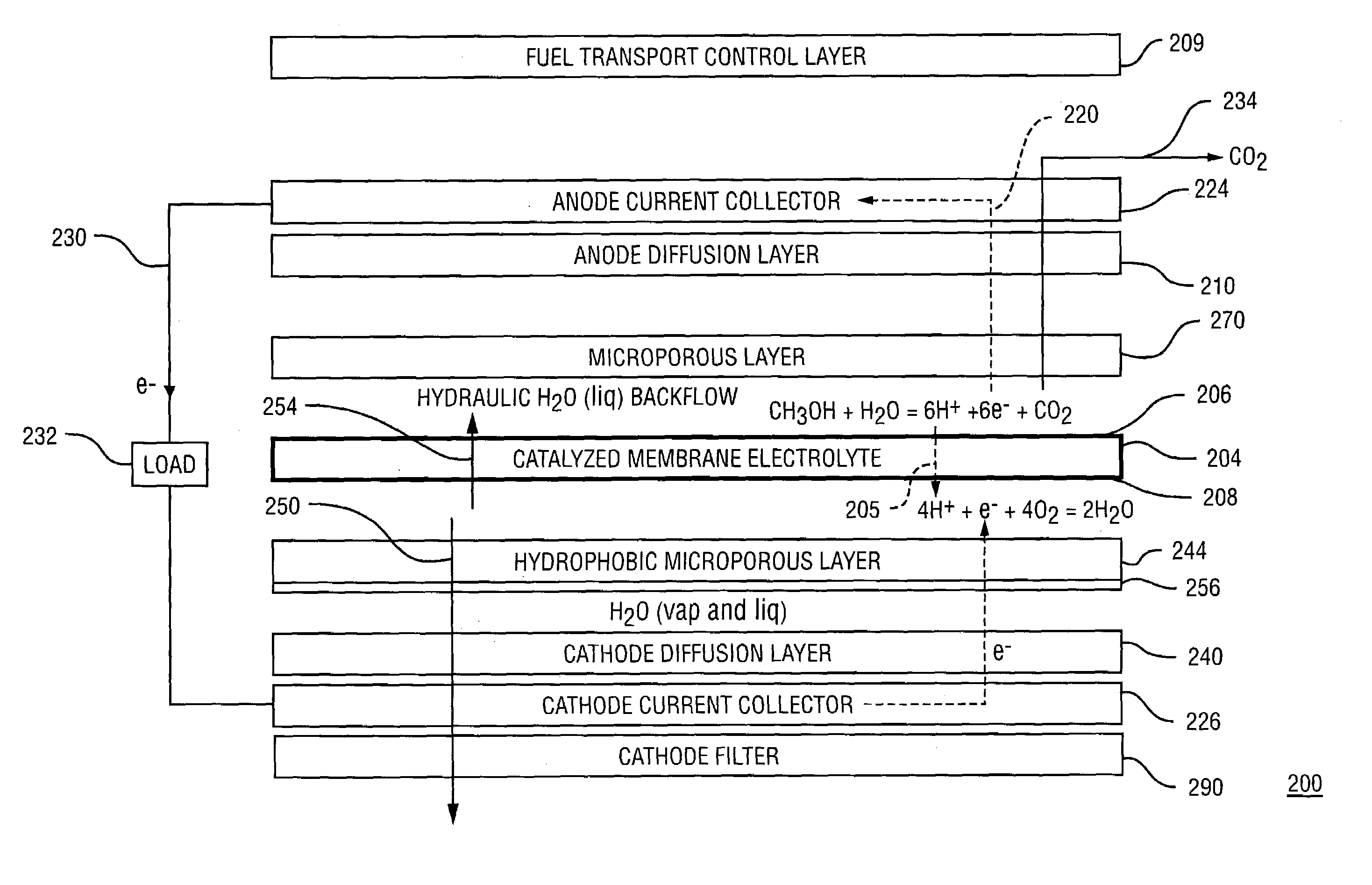
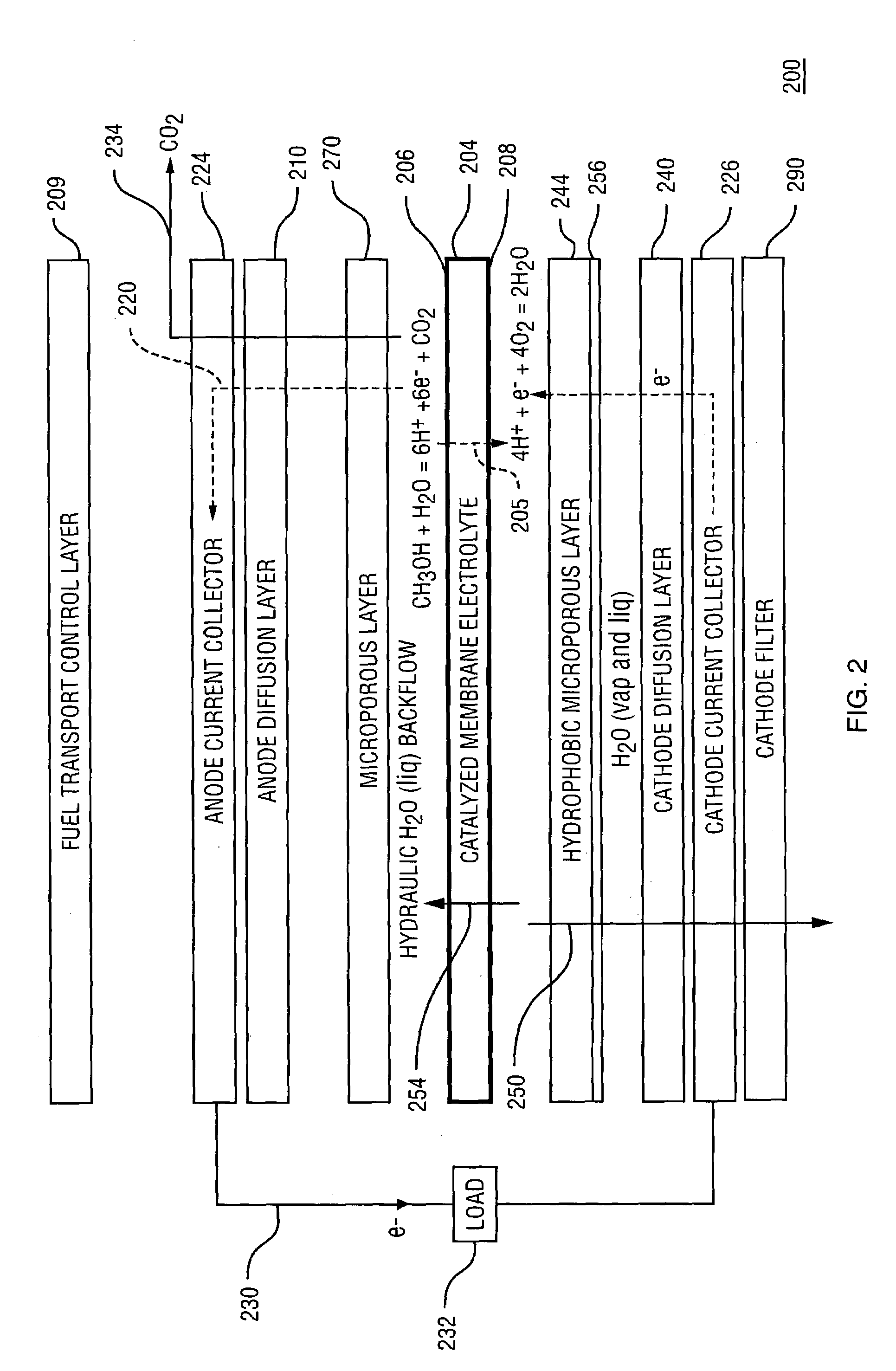
[0026]In accordance with the present invention, instead of actively circulating the water back into the anode, the invention described pushes
liquid water back from the cathode to the anode through the
cell membrane. In accordance with one aspect of the present invention, a hydrophobic microporous layer is utilized as a water management membrane that is disposed in the cathode chamber of the fuel cell between the cathode
diffusion layer and the catalyzed membrane
electrolyte. In this way, water that is produced in the cathode
half reaction is blocked by the severe barrier to liquid water penetration presented by a microporous hydrophobic layer which consequently applies back
hydrostatic pressure which pushes water from the cathode back into and through the membrane
electrolyte. The water management element may be comprised of a film of
expanded PTFE (preferably impregnated with carbon microparticles to facilitate electronic conduction), or it may be a microporous layer, based on carbon microparticles impregnated with PTFE, attached to the carbon cloth or
carbon paper backing material. Regardless of its construction, this layer must be gas permeable to allow
oxygen to the
cathode catalyst while substantially preventing liquid water from escaping. Additional conditions for effective push-back of liquid water into the membrane, are effective bonding between the catalyst and water management layer and sufficient mechanical compression across the cell applied by appropriate framing, that keeps the microporous layer, or microporous film, well attached to the catalyst layer even as
water pressure builds up at this interface in a cell under current.
[0027]The unique features of the present invention allow this optimized water distribution in the cell to be maintained, even when neat
methanol is directly supplied from the fuel
cartridge (or reservoir). The present invention enables to deliver the neat fuel at the appropriate rate into the anode chamber as required to achieve an optimized, low concentration in contact with the anode face of the catalyzed membrane, to which face water is effectively supplied internally across the membrane from the cathode. As noted herein, the desirable reaction at the anode is process (1), which involves one molecule of methanol and one molecule of water, and in order for this reaction to proceed the rate of methanol supply has to be controlled such that a sufficient amount of water that is needed for process (1) to occur, flows back from the cathode into the anode chamber.
[0031]In order to satisfy all of these considerations, the present invention provides a fuel transport barrier, which, in one embodiment of the invention is a methanol vapor delivery film, which is typically placed between the fuel source and the catalyzed membrane electrolyte and along the same plane as of the catalyzed membrane electrolyte. The transport barrier is in such case comprised of a thin, phase-changing “
pervaporation” film that acts as a controlled
fuel delivery barrier between a concentrated methanol source and anode face of the membrane electrolyte
assembly. The methanol delivery film controls the rate of fuel transport across the film, as set by selecting a material, or materials for the film and the film thickness. The inventive anode transport barrier allows the use of a neat methanol feed, yet defines a controlled rate of
fuel delivery to result, following mixing with the internally supplied water from the cathode, in the appropriate low concentration of methanol at the
anode catalyst. The methanol delivery film may be integrated as part of a
cartridge or can be part of the fuel
cell system itself, when fuel is stored internal to the system.

