Apparatus and method for forming thin film using upstream and downstream exhaust mechanisms

a technology of exhaust mechanism and thin film, applied in the direction of coating, basic electric elements, chemical vapor deposition coating, etc., to achieve the effect of reducing the impact of purge gas

Active Publication Date: 2008-08-05
ASM JAPAN
View PDF4 Cites 262 Cited by
  • Summary
  • Abstract
  • Description
  • Claims
  • Application Information

AI Technical Summary

Benefits of technology

[0006]One of the merits of the showerhead method, however, is that it can supply a precursor on a substrate with uniform concentration distribution or arbitrary concentration distribution. In order to achieve uniform concentration distribution, controlling conductance in a flow path from the showerhead to the substrate by the dispersion plate is required; this becomes a main cause for impeding reaction gas purge from within the showerhead. In view of this, the inventors of the present invention have devised a method of supplying source gases onto a substrate surface at a uniform source gas concentration; reducing precursor concentration changes in a peripheral portion of the substrate when the gases are exhausted from the center of the showerhead toward its outer perimeter; and particularly, decreasing an impact of purge gas which prevents source gases from diffusing to a lower portion of a substrate-placing stand as well as eliminating source gases from within the showerhead or a reaction chamber in a short amount of time when a first source gas is switched to a second source gas.
[0024]The thin-film formation apparatus, which is characterized in that a space below the substrate-placing stand and a space above the substrate-placing stand are communicatively connected through a space having a narrow width within a processible range (e.g., approx. 0.5 mm to approx. 1.5 mm) and a long distance (e.g., approx. 10 mm to approx. 30 mm); and which is characterized in that a width and a length of the space are set so that diffusion of a source gas to the space below the placing stand from the space above it is prevented by the space having the narrow width by supplying an inert gas from below the substrate-placing stand;
[0026]The thin-film formation apparatus, which is characterized by being configured so that the first exhaust port is disposed to surround the side portion of the substrate-placing stand, and a width (e.g., approx. 2 mm to approx. 5 mm) of a gas flow path of the first exhaust port, which is located on the side of the substrate-placing stand on the gas-dispersion plate side (or a gas flow path extending from the top surface's outer circumferential portion of the substrate-placing stand to the first exhaust port), is wider than a width (e.g., approx. 0.5 mm to approx. 1.5 mm) of a gas flow path of the first exhaust port, which is located in a lower portion of the substrate-placing stand (or a gas flow path on the side of the substrate-placing stand further down from the first exhaust port); by being configured so that diffusion of source gases to the downward space from the upward space through the upper and lower gas flow paths (upward and downward gas flow paths sandwiching the first exhaust port) is prevented by supplying an inert gas (purge gas) from below the substrate-placing stand and that the purge gas from the downward space does not produce an effect on a substrate being in the upward space (i.e., problems of dilution of the source gas by the purge gas, etc. are decreased) by securing a distance of a gas flow path from an outer circumferential edge of the substrate in the upward space to the first exhaust port (e.g., approx. 10 mm-approx. 45 mm).
[0039]The method for forming a thin film, wherein gas discharged from the first gas flow path is exhausted from over the placing stand, and then from the first exhaust port; and an inert gas used for preventing source gas diffusion, which is introduced from a position downward of the placing stand, is exhausted from the first exhaust port along with the side of the placing stand; and at this time, in order to prevent a process gas from diffusing to the lower side of the placing stand and to minimize an impact on the placing stand, the inert gas is adapted to be smoothly exhausted from the first exhaust port;
[0051]In accordance with one embodiment of the thin-film formation apparatus according to the present invention, it becomes possible to supply source gases extremely uniformly by using a showerhead and to eliminate reaction gases remaining inside the showerhead in a short period of time, which were conventionally difficult. For example, by using a high-speed variable-conductance valve powered by a servomotor, it becomes possible to make conductance 2-3 digits variable at a high speed of approx. 50 msec, thereby enabling to achieve purging of remaining gases thoroughly in a short period of time. Additionally, by using a valve which can be opened / closed at a high speed, the same effect can be obtained if long-term reliability of the valve is secured. Consequently, forming uniform films with improved throughput, which was conventionally unthinkable, becomes possible.

Problems solved by technology

In order to achieve uniform concentration distribution, controlling conductance in a flow path from the showerhead to the substrate by the dispersion plate is required; this becomes a main cause for impeding reaction gas purge from within the showerhead.

Method used


Image

  • Apparatus and method for forming thin film using upstream and downstream exhaust mechanisms
  • Apparatus and method for forming thin film using upstream and downstream exhaust mechanisms
  • Apparatus and method for forming thin film using upstream and downstream exhaust mechanisms

Examples


embodiment 1

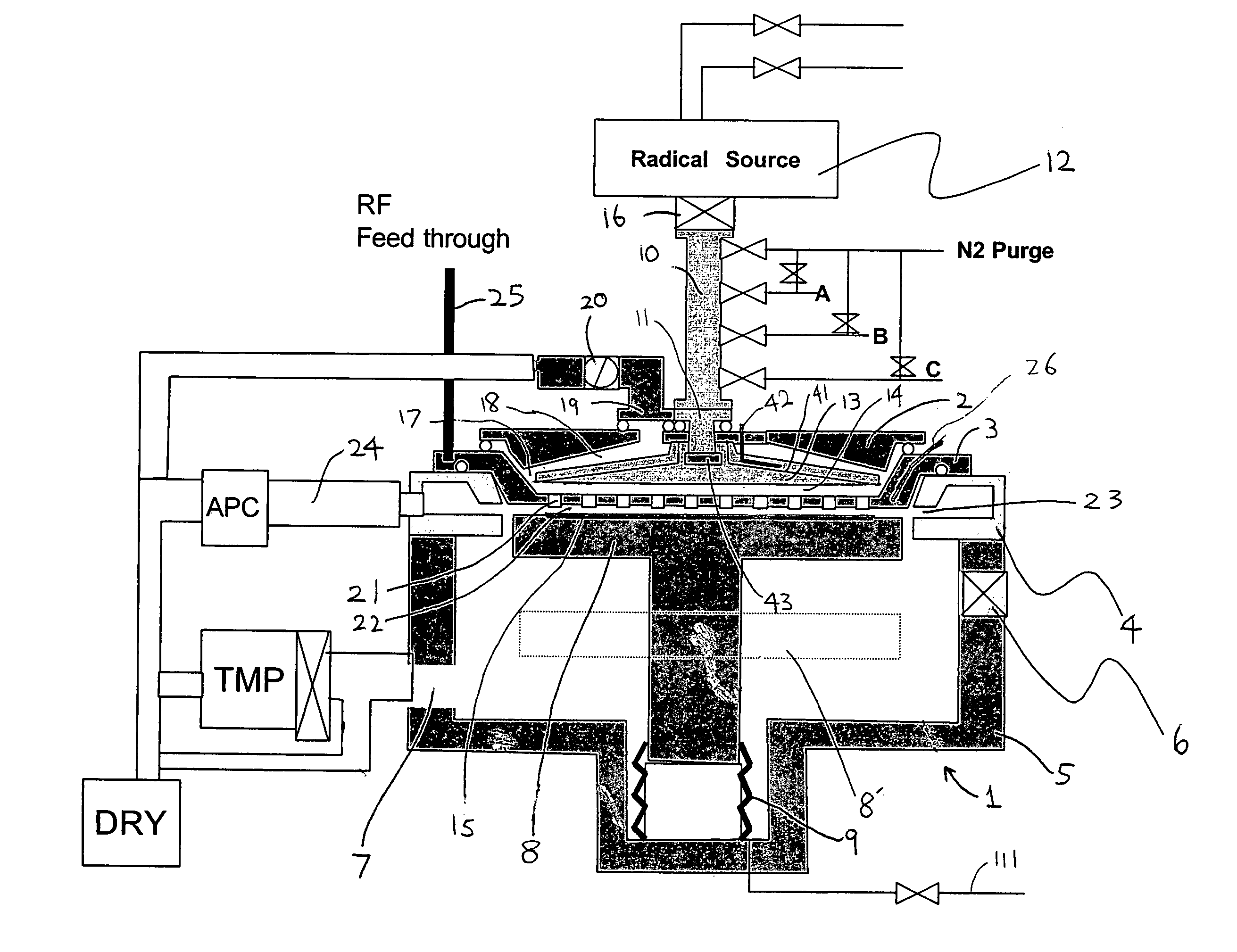
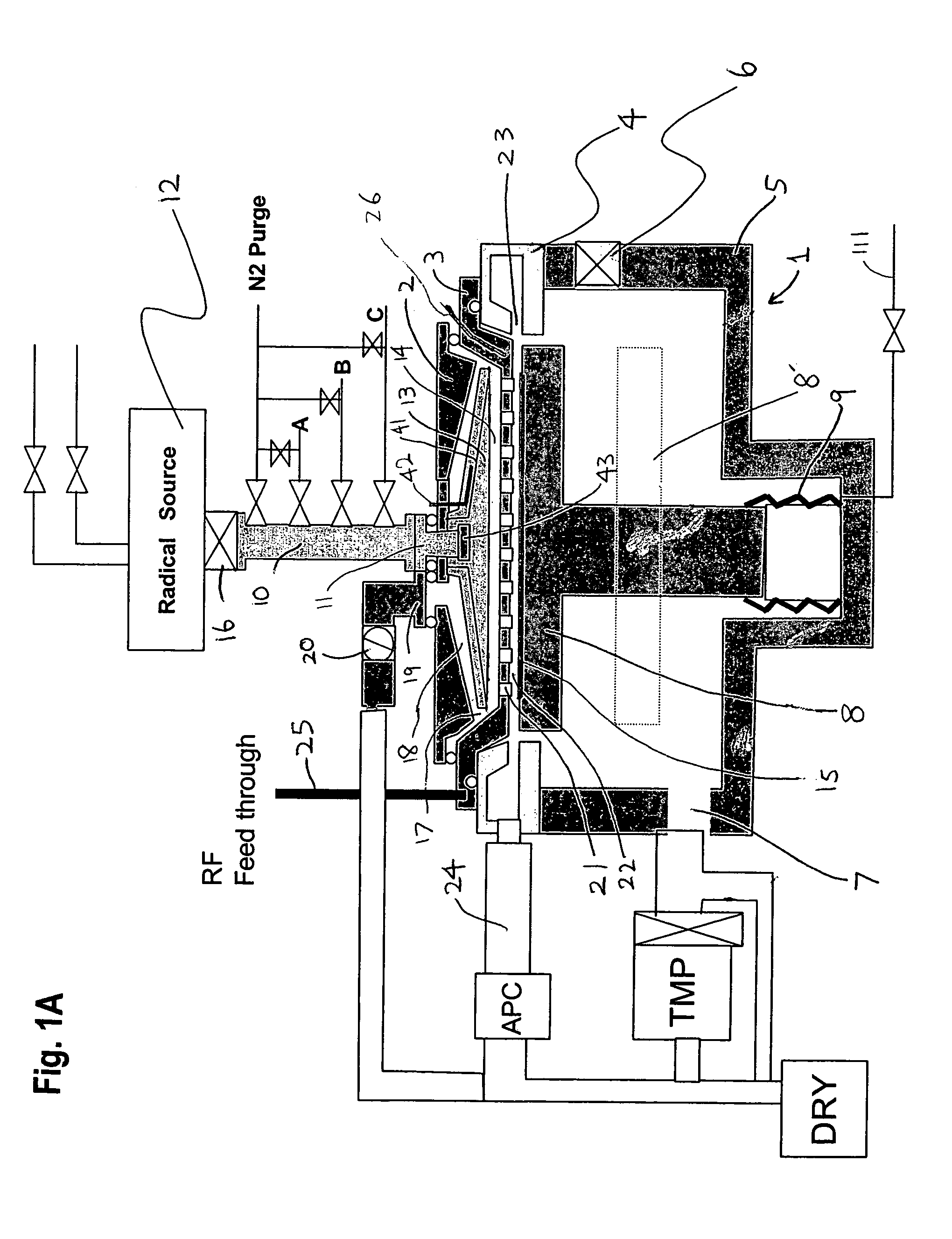
[0222]In this embodiment, a process of forming tungsten carbide nitride (WCN) films using tungsten hexafluoride (WF6), ammonia (NH3) and tetraethoxyboron (TEB) is described. After a silicon substrate is transferred from a vacuum transfer chamber (not shown in the figure) to the reaction chamber 1, remaining moisture, oxygen, etc. are exhausted thoroughly using a turbo pump (See FIG. 1A). The substrate is moved to a given position by a vertical-movement mechanism of the substrate-heating stand 8. At this time, a gap between the dispersion plate 3 and a substrate surface is set at a value within the range of 2-8 mm (1-10 mm according to one embodiment; 3, 4, 5, 6, 7, 8, 9 mm, and values between each value can be taken). In this embodiment, the process was implemented by setting the gap at 5 mm.

[0223]FIG. 3 and FIG. 4 show a process sequence: A silicon substrate is transferred from a vacuum transfer chamber (not shown) to the reaction chamber 1. The reaction chamber is exhausted by the...

embodiment 2

[0250]In this embodiment, a process of forming tantalum nitride films using tertiaryamylimidotris(dimethylamido)tantalum: TaN(C4H9)(NC2H6)3, an organic metal material of Ta, and NH3. After a silicon substrate is transferred from a vacuum transfer chamber (not shown in the figure) to the reaction chamber 1, remaining moisture, oxygen, etc. are evacuated satisfactorily using a turbo pump 7 (See FIG. 1A). The substrate is moved to a given position by a vertical movement mechanism of the substrate-heating stand 8. At this time, a gap between the dispersion plate 3 and a substrate surface is set at a value within the range of 2-8 mm. In this embodiment, the process was implemented by setting the gap at 5 mm.

[0251]FIG. 5 and FIG. 6 show a process sequence: A silicon substrate is transferred from a vacuum transfer chamber (not shown) to the reaction chamber 1. The reaction chamber is exhausted by the turbo pump to 10−6 Torr or below. After an amount of remaining gases including moisture an...


PUM

PropertyMeasurementUnit
temperatureaaaaaaaaaa

Abstract

A thin-film formation apparatus possesses a reaction chamber to be evacuated, a placing portion on which a substrate is placed inside the reaction chamber, a gas-dispersion guide installed over the placing portion for supplying a gas onto a substrate surface, a gas-supply port for introducing the gas into the gas-dispersion guide, a gas-dispersion plate disposed on the side of the substrate of the gas-dispersion guide and having multiple gas-discharge pores, a first exhaust port for exhausting, downstream of the gas-dispersion plate, the gas supplied onto the substrate surface from the gas-dispersion plate, and a second exhaust port for exhausting, upstream of the gas-dispersion plate, a gas inside the gas-dispersion guide via a space between the gas-dispersion guide and the gas-dispersion plate.

Description

[0001]This application claims the benefit of U.S. Provisional Application No. 60 / 510,059, filed on Oct. 9, 2003.BACKGROUND OF THE INVENTION[0002]1. Field of the Invention[0003]The present invention relates to a single-wafer-processing type thin-film formation apparatus and method, which form a thin film on a workpiece, which is a semiconductor wafer, piece by piece.[0004]2. Description of the Related Art[0005]As thin-film formation apparatuses for thin film growth by atomic layer deposition, various types of formation apparatuses have been proposed. As typical examples, there are cases, in which gas is supplied from a gas-dispersion apparatus (i.e., a showerhead) disposed facing a substrate; and cases, in which gas is supplied by forming a laminar flow flowing in a direction from one edge of the substrate to the other edge without using the showerhead. In the case of a showerhead method, source gases can be supplied at uniform gas concentration onto the substrate surface, whereas in...

Claims


Application Information

Patent Timeline
Patent Type & Authority Patents(United States)
IPC IPC(8): H01L23/62C23C16/455C23C16/34C23C16/44H01J37/32H01L21/205H01L21/306
CPCC23C16/34C23C16/4412C23C16/45525H01J37/32834C23C16/45565H01J37/3244H01J37/32449C23C16/45544
Inventor SHINRIKI, HIROSHIKAWANO, BAIEISHIMIZU, AKIRA
Owner ASM JAPAN
Why Eureka
Try Eureka