Memory write circuit

a write circuit and memory technology, applied in the field of memory devices, can solve the problems of difficult reliable readout at high speeds, low signal quality of mtjs on reading, so as to reduce signal loss and noise problems, and avoid switched ground connections

Inactive Publication Date: 2008-08-12
INFINEON TECH AG +1
View PDF10 Cites 65 Cited by
  • Summary
  • Abstract
  • Description
  • Claims
  • Application Information

AI Technical Summary

Benefits of technology

[0009]In various embodiments, the present invention provides a design for a memory array that uses bi-directional current for writing, and that avoids switched ground connections for memory cells, thereby reducing signal loss and noise problems. In accordance with an embodiment of the invention, this is achieved by connecting a ground connection of each memory cell to a fixed ground, which cannot be switched. To supply the bi-directional current that is needed to write to memory cells, positive and negative current sources are provided. These current sources may be selectively connected to bit lines, that are electrically connected to the memory cells. Applying a positive current, from the positive current source, through a memory cell writes a “1”, and applying a negative current, from the negative current source through a memory cell writes a “0”. In one embodiment, this technique is applied to a spin injection magneto-resistive random access memory (MRAM) device, in which each memory cell includes a magnetic tunnel junction (MTJ).

Problems solved by technology

One problem with MRAM devices is that the signals provided by MTJs on reading are small relative to the signals provided by other non-volatile memory technologies.
This small signal makes reliable readout at high speeds difficult, and generally requires that the sense amplifier that is used to read MRAM memory use as much of the cell signal as possible.
While providing a low resistive ground connection is relatively straightforward when the memory cells can be permanently tied to ground, it can be difficult when the ground connection has to be switched, as is typically the case in spin-injection MRAM, and in other types of memory that use bi-directional current for writing.
Because it must be able to force a write current through the MTJ in either direction, typical spin-injection MRAM designs do not have fixed ground connections.
This causes noise and signal loss in the sensing path of spin-injection MRAM devices.
Similar problems may be encountered in other memory devices that use bi-directional current for writing.

Method used


Image

  • Memory write circuit
  • Memory write circuit
  • Memory write circuit

Examples


Embodiment Construction

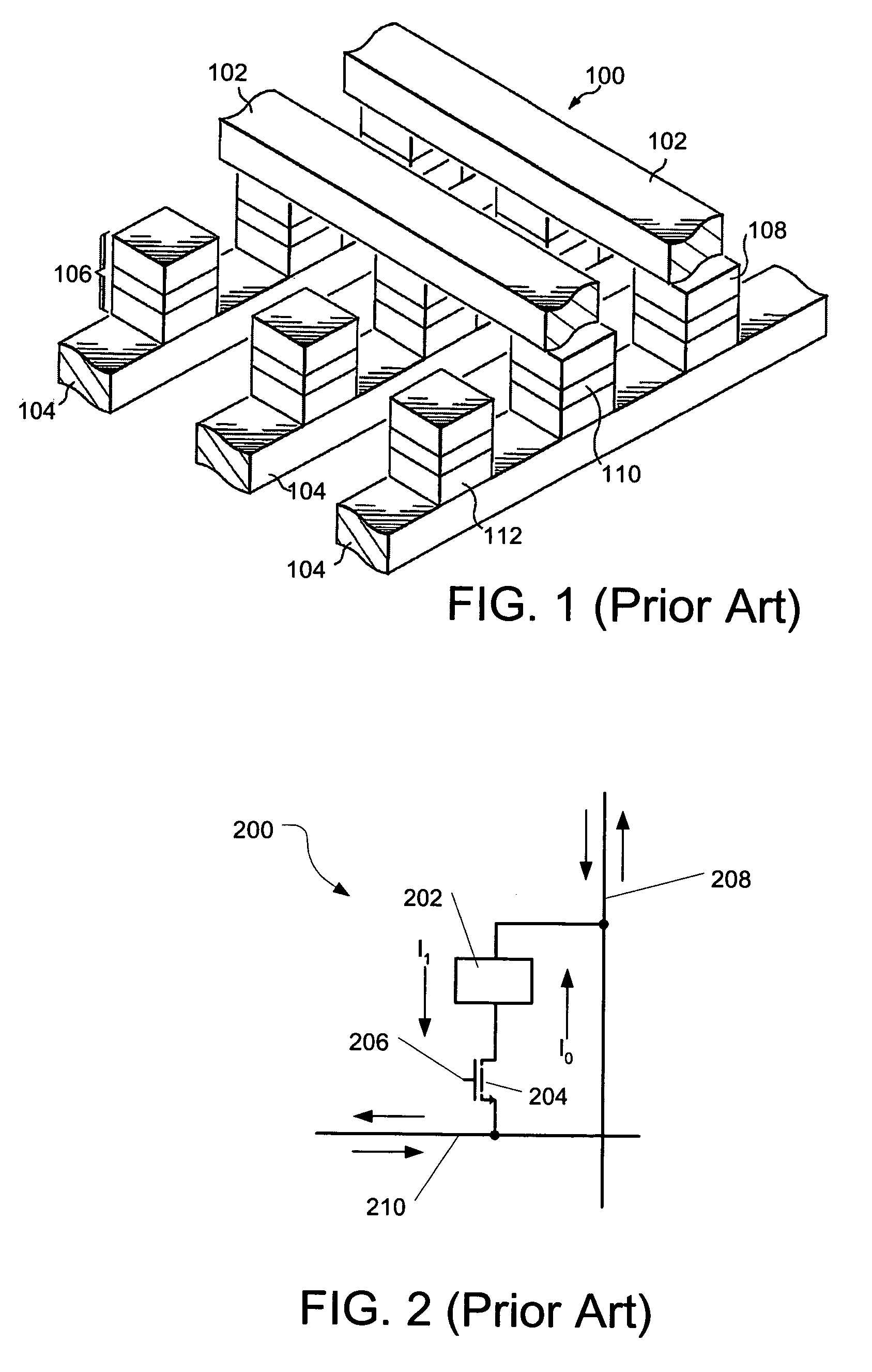
[0015]FIG. 1 shows a perspective view of a typical prior art MRAM array 100 having bit lines 102 disposed in an orthogonal direction to word lines 104 in adjacent metallization layers. Magnetic memory stacks 106 are electrically coupled to the bit lines 102 and word lines 104 (collectively, write lines), and are positioned between the bit lines 102 and word lines 104 at locations where a bit line 102 crosses a word line 104. The magnetic memory stacks 106 are preferably magnetic tunnel junctions (MTJs), comprising multiple layers, including a free layer 108, a tunnel layer 110, and a fixed layer 112. The free layer 108 and fixed layer 112 preferably comprise a plurality of magnetic metal layers (not shown). These magnetic metal layers may, for example, comprise eight to twelve layers of materials such as PtMn, CoFe, Ru, and NiFe. The tunnel layer 110 comprises a dielectric, such as Al2O3.

[0016]The fixed layer 112 is preferably magnetized in a fixed direction, while the direction of ...


PUM


Abstract

A design for a memory array that uses bi-directional write currents and that avoids switched ground connections for memory cells, thereby reducing signal loss and noise problems is described. Positive and negative current sources are provided to supply the bi-directional current that is used to write to a memory cell. These current sources may be selectively connected to bit lines that are electrically connected to the memory cells. Applying a positive current, from the positive current source, through a memory cell writes a “1”, and applying a negative current, from the negative current source, through a memory cell writes a “0”. Use of both a positive and a negative current source enables writing to the memory cells without relying on a switched ground connection to provide bi-directional current. This permits a ground connection of each memory cell to be connected to a fixed ground. An example in which this design is used with a spin injection magneto-resistive random access memory (MRAM) device is shown.

Description

TECHNICAL FIELD[0001]The present invention relates generally to memory devices, and in one embodiment to the design of a write circuit for a memory device.BACKGROUND[0002]One emerging technology for non-volatile memory is magneto-resistive random access memory (MRAM). A common form of MRAM is based on the tunnelling magneto-resistance (TMR) effect, in which each memory cell comprises a magnetic tunnel junction (MTJ). Such an MTJ may be formed from two ferromagnetic metal layers, with an insulating layer placed between the metal layers. When a voltage is applied between the metal layers, a tunnel current flows. The tunnel resistance varies based on the relative directions of magnetization of the metal layers. The tunnel resistance is small when the directions of magnetization are parallel (typically representing a “0”), and large (approximately 10%-20% higher, at room temperature) when the directions of magnetization are anti-parallel (typically representing a “1”).[0003]The metal la...

Claims


Application Information

Patent Timeline
Patent Type & Authority Patents(United States)
IPC IPC(8): G11C11/00
CPCG11C7/02G11C11/16G11C7/12
Inventor GOGL, DIETMAR
Owner INFINEON TECH AG
Why Eureka
Try Eureka