Thermodynamic cycles using thermal diluent

Active Publication Date: 2008-08-26
VAST HLDG LLC
View PDF42 Cites 169 Cited by
  • Summary
  • Abstract
  • Description
  • Claims
  • Application Information

AI Technical Summary

Benefits of technology

[0017]With many energy conversion systems and thermodynamic cycles, there is a desire to reduce system life cycle costs and emissions and improve performance and reliability. There is similar inter

Problems solved by technology

The prior art includes combustors and combustion systems that use diluents to cool combustion with relatively poor control over the peak temperature and little spatial control over the transverse temperature profile.
Pressurizing this excess air along commonly consumes 40% to 70% (from large turbines to microturbines) of the gross turbine power recovered resulting in low net specific power.
It is difficult to control the temperature profile using excess air or steam as commonly used to cool cycle components and special mixing devices.
The problem of temperature irregularities is heightened by changes in work load.
This results in high capital costs.
By only being able to deliver steam, the STIG cycle is limited in its ability to recover lower temperature heat.
High water treatment costs and water availability are often stated as a major objections to more widespread use of the STIG.
This is similarly limited by the air saturation limit.
While utilizing lower quality water, the HAT and EvGT cycles are limited in the amount of deliverable diluent by air saturation limits.
Otherwise these RWI, HAT, and EvGT cycles have been little used, possibly because of relatively high capital costs.
It has lower costs but lower efficiency than the HAT cycle.
Conventional heat recovery methods have particular difficulty in recovering useful heat below the temperature of steam formed from

Method used


Image

  • Thermodynamic cycles using thermal diluent
  • Thermodynamic cycles using thermal diluent
  • Thermodynamic cycles using thermal diluent

Examples


Example

[0088]General

[0089]U.S. Pat. Nos. 3,651,641, 5,617,719, 5,743,080 and 6,289,666 to Ginter teach VAST thermodynamic power cycles that primarily pump liquid thermal diluent (such as water) into a thermodynamic cycle to cool the combustion, reducing the use of excess dilution air. This VAST (“Value Added Steam Technology”) cycle is a hybrid between the Brayton and Rankine cycles and preferably uses fluid water as diluent. It uses an energetic fluid formed in a VAST direct contact fluid combustor, containing both hot products of combustion and superheated steam. This hot energetic fluid is preferably expanded through an expander to generate shaft and / or electrical power. E.g., via a turbine or reciprocating engine. It may also provide Combined Heat and Power (CHP).

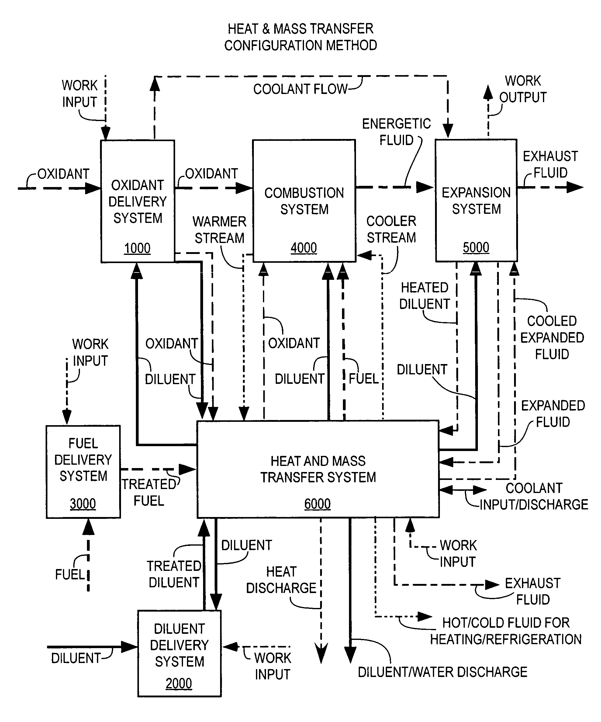
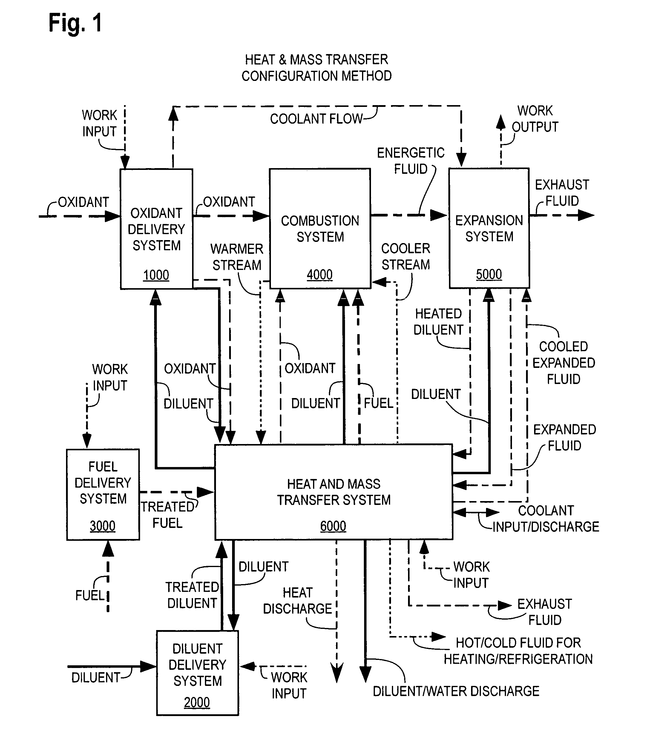
[0090]With reference to FIG. 1, the VAST thermodynamic cycles utilize a Combustion System 4000 to form and deliver an Energetic Fluid to an Expansion System 5000 forming an expanded fluid and delivering Work Output. E.g., expa...


PUM


Abstract

A thermodynamic system that produces mechanical, electrical power, and/or fluid streams for heating or cooling. The cycle contains a combustion system that produces an energetic fluid by combustion of a fuel with an oxidant. A thermal diluent may be used in the cycle to improve performance, including but not limited to power, efficiency, economics, emissions, dynamic and off-peak load performance, and/or turbine inlet temperature (TIT) regulation and cooling heated components. The cycle preferably includes a heat recovery system and a condenser or other means to recover and recycle heat and the thermal diluent from the energetic fluid to improve the cycle thermodynamic efficiency and reduce energy conversion costs. The cycle may also include controls for temperatures, pressures, and flow rates throughout the cycle, and controls power output, efficiency, and energetic fluid composition.

Description

PRIORITY INFORMATION[0001]This application claims the priority benefit under 35 U.S.C. § 119(e) of Provisional Application 60 / 442,096, filed Jan. 22, 2003 and Provisional Application 60 / 442,844 filed Jan. 24, 2003.BACKGROUND OF THE INVENTION[0002]1. Field of the Invention[0003]The invention relates in general to methods of performing thermodynamic cycles for generating mechanical and electrical power, heating, or cooling.[0004]2. Description of the Related Art[0005]The prior art includes combustors and combustion systems that use diluents to cool combustion with relatively poor control over the peak temperature and little spatial control over the transverse temperature profile. Cooling of the combustion products has commonly been done with excess air. Pressurizing this excess air along commonly consumes 40% to 70% (from large turbines to microturbines) of the gross turbine power recovered resulting in low net specific power. I.e., the gross power less compressor and pump power produ...

Claims


Application Information

Patent Timeline
IPC IPC(8): B60H1/02B01FB01J8/02B01J10/00B01J12/00F01KF01K1/00F01K21/04F23C6/02F23C99/00F23K5/04F23L7/00F23N1/00F23N3/00F23N5/00F23R3/00F23R3/28
CPCF01K21/047F23C6/02F23C99/001F23L7/002F23R3/28F23C99/003Y02E20/16
Inventor HAGEN, DAVID L.GINTER, GARYTRAVERSO, ALBERTOGOHEEN, BILLMCGUIRE, ALLANRANKIN, JANETMASSARDO, ARISTIDEKLAUS, RONALD L.
Owner VAST HLDG LLC
Why Eureka
Try Eureka