Composite sintered magnetic material, its manufacturing method, and magnetic element using composite sintered magnetic material

a technology of composite sintered magnetic material and manufacturing method, which is applied in the direction of magnetic materials, magnetic bodies, textiles and paper, etc., can solve the problems of low saturation magnetic flux density of ferrite magnetic core, poor direct-current superposition characteristic, and noise generation

Inactive Publication Date: 2008-09-09
PANASONIC CORP
View PDF13 Cites 21 Cited by
  • Summary
  • Abstract
  • Description
  • Claims
  • Application Information

AI Technical Summary

Problems solved by technology

A ferrite magnetic core is low in saturation magnetic flux density, and poor in direct-current superposing characteristic.
However, such a wide gap causes a humming noise to be generated, and magnetic flux leakage from the gap causes the winding especially at a high-frequency band to be remarkably increased in copper loss.
However, it cannot be said that a powder magnetic core is more excellent than a ferrite magnetic core with respect to permeability and core loss.
Particularly, in the case of a powder magnetic core used for a choke coil and inductor, the core is greatly increased in temperature because of remarkable core loss, making it difficult to reduce the size.
Therefore, it is extremely difficult to manufacture small-sized powder magnetic cores used for choke coils which are mounted in products with complicated shapes such as DC-DC converters for computers and required to be low in height.
Accordingly, a powder magnetic core is subjected to greater restrictions as a core shape as compared with a ferrite magnetic core, and it is difficult to reduce the size of the product.
On the other hand, regarding the hysteresis loss, since a powder magnetic core is compacted under a high pressure, considerable strain is introduced into the magnetic material, causing the permeability to be lowered and the hysteresis loss to be increased.
However, in the case of powder magnetic core 104 in the conventional example wherein ferrite being a magnetic material is filled between metal powder 105, the bonding between metal powder 105 and ferrite layer 106 is not enough to assure sufficient mechanical strength, and there arises a problem of impact resistance.
In that case, there is a problem of cracking in the machining surface or partial peeling and removing.

Method used


Image

  • Composite sintered magnetic material, its manufacturing method, and magnetic element using composite sintered magnetic material
  • Composite sintered magnetic material, its manufacturing method, and magnetic element using composite sintered magnetic material
  • Composite sintered magnetic material, its manufacturing method, and magnetic element using composite sintered magnetic material

Examples


embodiment 1

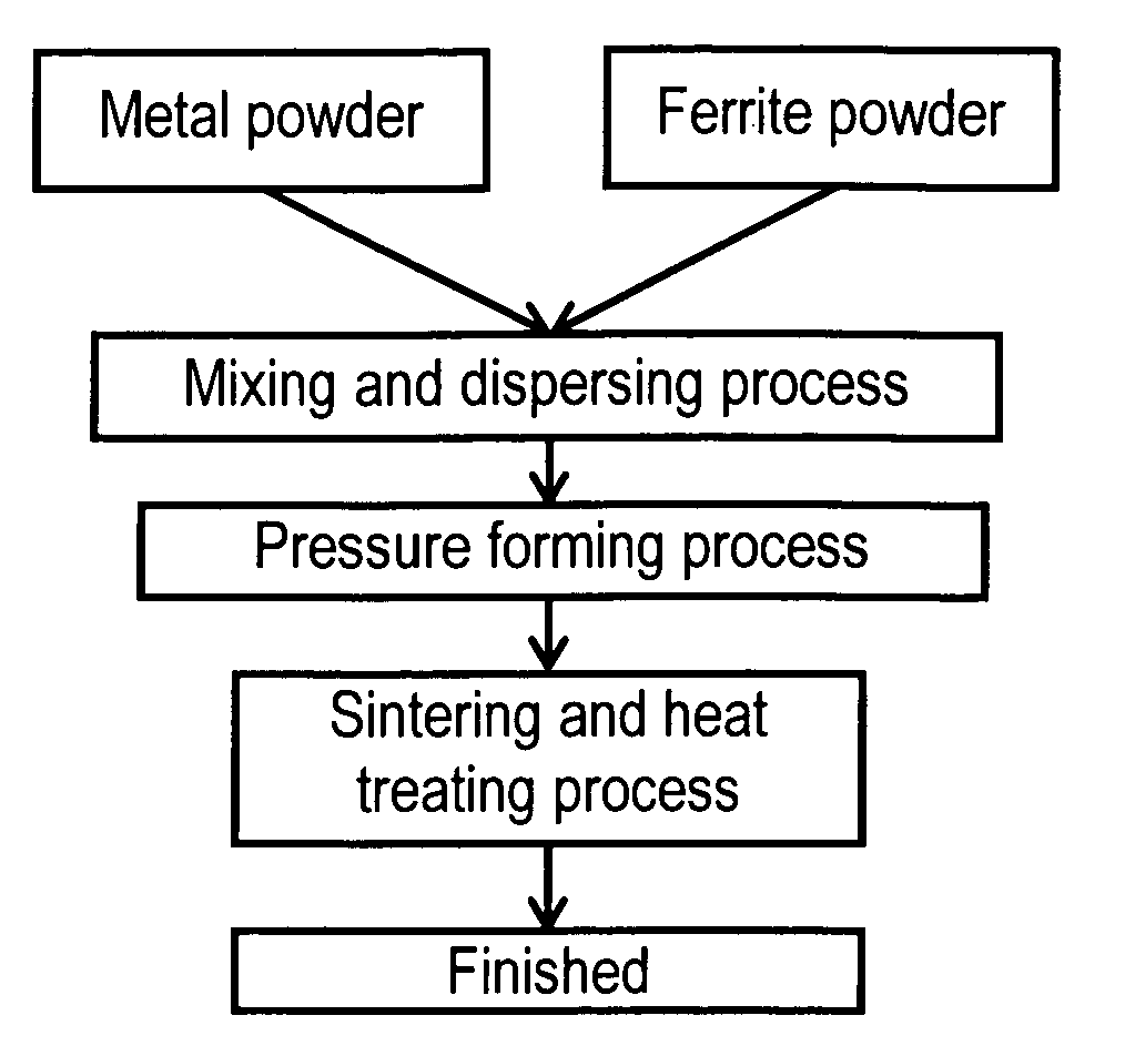
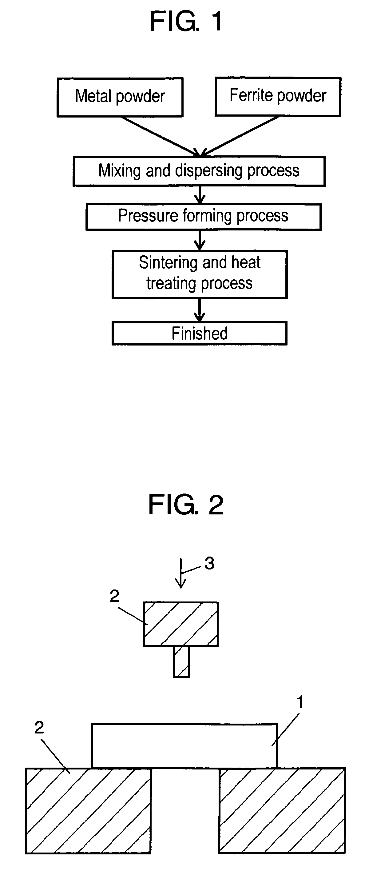
[0046]In the embodiment 1, as shown in the block diagram of FIG. 1, ferrite powder of 0.6 μm in average grain size is added by 15 wt % to metal powder of 8 μm in average grain size, and both are mixed and dispersed. After that, pressure forming, sintering, and heat treatment are performed, thereby, manufacturing a composite sintered magnetic material having a shape of about 15 mm in outer dimension, 10 mm in bore diameter, and 3 mm in height.

[0047]FIG. 7 shows the characteristics of a composite sintered magnetic material in the embodiment 1. Samples No. 6, 7 are powder magnetic cores using metal powder, and samples No. 8, 9 are ferrite magnetic cores. Samples No. 6 to 9 are the examples for comparison with the composite sintered magnetic material in the embodiment 1. The compositions of metal powder and ferrite powder used in the embodiment 1 are as mentioned in FIG. 7.

[0048]In FIG. 7, permeability was measured at frequency 100 kHz by using an LCR meter, and core loss was measured a...

embodiment 2

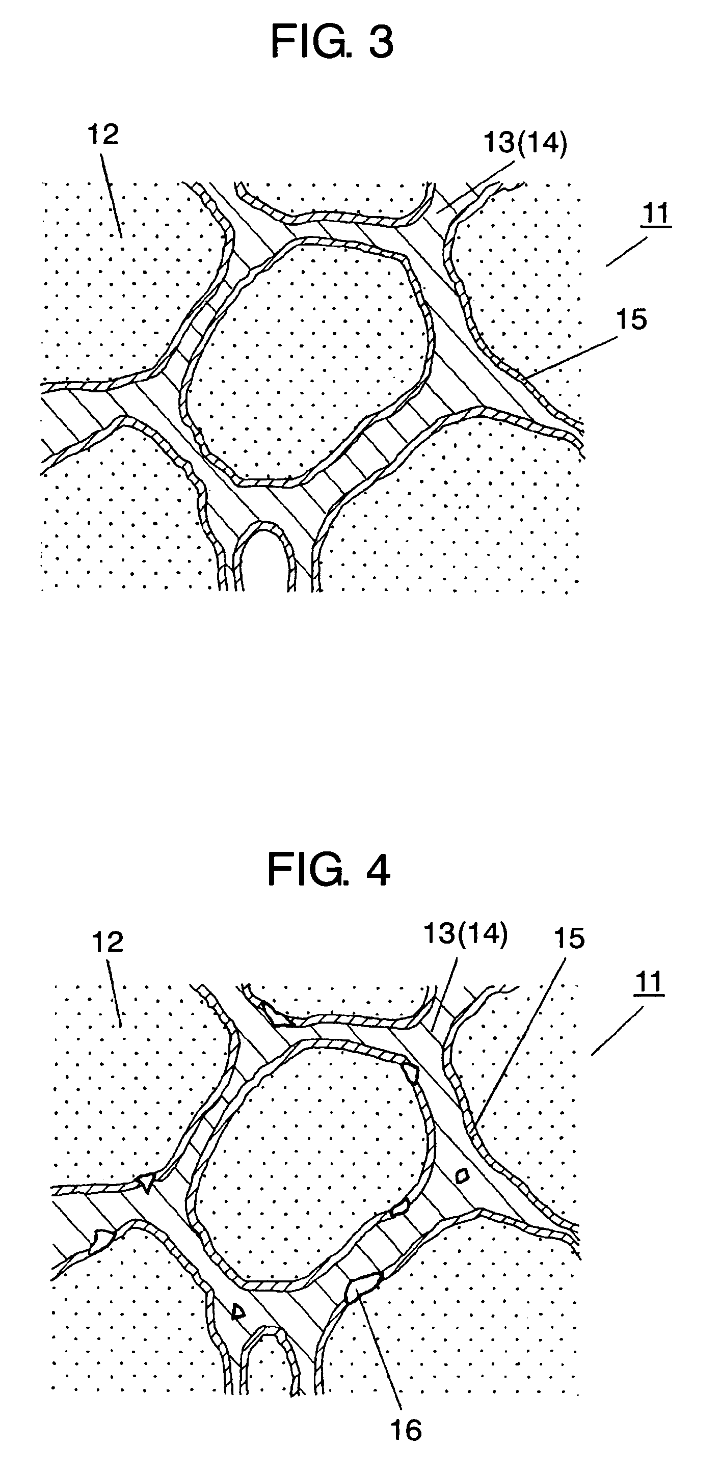
[0077]In the embodiment 2 of the present invention, the surface of metal powder 12 is coated with ferrite layer 13, for example, by a non-electrolytic plating, coprecipitation, mechanofusion, evaporation, sputtering process, and the like. After that, metal powder 12 coated with ferrite layer 13 is compacted under pressure and the compact obtained is sintered, thereby forming diffusion layer 15 between metal powder 12 and ferrite layer 13. In this way, it is possible to omit the mixing and dispersing process from the manufacturing method for composite sintered magnetic material 11 in the embodiment 1. Also, by using the method shown in the embodiment 2 of the present invention, it is possible to assure the existence of ferrite layer 13 between metal powder 12. As a result, it becomes possible to realize excellent high-frequency characteristic while assuring the insulation in composite sintered magnetic material 11.

[0078]FIG. 5 shows a block diagram of the manufacturing method for com...

embodiment 3

[0086]In the embodiment 3 of the present invention, raw ferrite is used instead of ferrite powder 14. It is possible to use NiO, Fe2O3, ZnO, CuO, MgO, and MnCo3 as raw ferrite. In this case, predetermined amounts of metal powder 12 and raw ferrite are measured, then mixed and dispersed, followed by compacting under pressure, and the compact is sintered to change the raw ferrite into ferrite, and diffusion layer 15 can be formed between metal powder 12 and ferrite layer 13.

[0087]Besides the above method, in the manufacturing method shown in the embodiment 2, it is also possible to form diffusion layer 15 between metal powder 12 and ferrite layer 13 by coating the surface of metal powder with raw ferrite instead of ferrite powder 14, for example, by non-electrolytic plating, coprecipitation, mechanofusion, evaporation, sputtering process and the like, followed by pressure forming metal powder 12 coated with the raw ferrite and sintering the compact obtained.

[0088]Further, it is possib...


PUM

PropertyMeasurementUnit
temperatureaaaaaaaaaa
grain sizeaaaaaaaaaa

Abstract

A composite sintered magnetic material comprises a kind of metal powder at least one selected from the group consisting of Fe, Fe—Si type, Fe—Ni type, Fe—Ni—Mo type, and Fe—Si—Al type, and a ferrite layer formed from a kind of ferrite powder at least one selected from the group consisting of Ni—Zn type, Mn—Zn type, and Mg—Zn type, wherein a diffusion layer is formed by sintering between both of these to integrates the both.

Description

FIELD OF THE INVENTION[0001]The present invention relates to a composite sintered magnetic material used for transformers, choke coils, or magnetic heads, its manufacturing method, and a magnetic element using the composite sintered magnetic material.BACKGROUND OF THE INVENTION[0002]Recently, there is a trend toward reduction in size of electric and electronic apparatuses, and a magnetic material is also required to be smaller in size and higher in efficiency. As a conventional magnetic material, for example, there are a ferrite magnetic core using ferrite powder for a choke coil used in a high-frequency circuit and a powder magnetic core that is a metal powder compact.[0003]A ferrite magnetic core is low in saturation magnetic flux density, and poor in direct-current superposing characteristic. Accordingly, in a conventional ferrite magnetic core, there is provided a gap of 200 to 300 μm in a direction vertical to the magnetic path in order to assure direct-current superposing char...

Claims


Application Information

Patent Timeline
Patent Type & Authority Patents(United States)
IPC IPC(8): H01F1/33C22C33/02B22F3/24H01F1/147H01F1/34H01F41/02
CPCH01F1/33H01F1/1475H01F1/14766H01F1/344Y10S428/90Y10T428/12028Y10T428/12056Y10S428/928Y10T428/12465
Inventor TAKAHASHI, TAKESHIMATSUTANI, NOBUYAONISHI, KAZUAKI
Owner PANASONIC CORP
Why Eureka
Try Eureka