Planar view sample preparation

a sample and planar view technology, applied in the field of sample preparation, can solve the problems of grid interference with the electron beam of the tem, time-consuming work, and inability to provide flip stages in all fib systems, and achieve the effect of facilitating the subjecting of the sample and facilitating the modification of the orientation of the charged particle beam sampl

Active Publication Date: 2008-09-09
FEI CO
View PDF19 Cites 78 Cited by
  • Summary
  • Abstract
  • Description
  • Claims
  • Application Information

AI Technical Summary

Benefits of technology

[0015]This invention facilitates altering the orientation a charged particle beam sample in a charged particle beam system and is useful, for example, for preparing a planar view TEM sample. In one embodiment, a probe comprising a shaft and having an angled tip define is attached to the sample. By rotating the shaft through a first angle, the sample orientation is rotated by a second angle. Knowing the orientation of the longitudinal shaft axis with respect to the sample stage plane, and knowing the angle of the probe tip with respect to the longitudinal shaft axis, one can determine an angle of rotation of the shaft that will rotate the sample orientation by precisely ninety degrees or by any other desired angle. For example, if the longitudinal axis of the shaft is oriented at 45 degrees with respect to the sample stage plane, and the probe tip surface is oriented at 45 degrees with respect to the shaft longitudinal axis, then by rotating the probe shaft 180 degrees, the sample is orientation is altered by ninety degrees, from horizontal to vertical. The sample can be rotated so that it is at a convenient angle for attaching to a TEM grid so that the sample can be thinned by a charged particle beam system without removing the sample from the system for reorientation and without requiring a special stage. Reorienting the sample can facilitate subjecting the sample to other processing, such as laser processing or scanning electron beam microscopy, and the invention is not limited to preparing TEM samples.

Problems solved by technology

Because a sample must be very thin for viewing with transmission electron microscopy (whether TEM or STEM), preparation of the sample can be delicate, time consuming work.
If the sample were attached in a horizontal orientation to a vertically oriented TEM grid, the sample would extend normal to the plane of the grid, and the grid would interfere with the electron beam of the TEM.
Such flip stages are not available in all FIB systems.

Method used


Image

  • Planar view sample preparation
  • Planar view sample preparation
  • Planar view sample preparation

Examples


Embodiment Construction

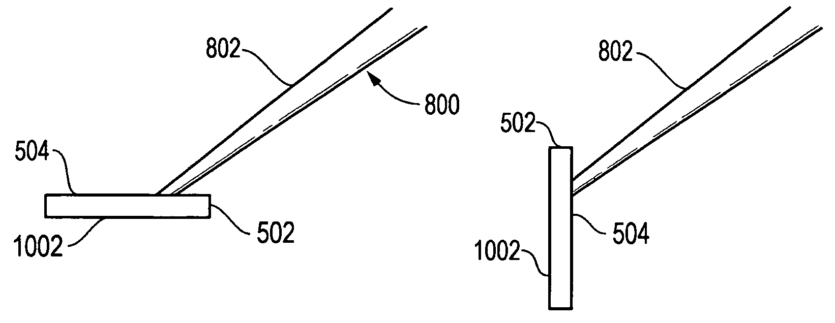
[0032]This disclosure relates to novel methods for altering the orientation of a sample in a charged particle beam system. In one embodiment, the invention facilitates preparation of a planar view sample for viewing in TEMs or STEMs. The methods provide for extracting and mounting a planar view sample onto a TEM grid in such a manner that the sample can be extracted, attached, and thinned without requiring a flip stage and without requiring that the TEM grid to be removed from the vacuum chamber and reoriented. Re-orienting the sample may also facilitate other analytical or processing operations on the sample.

[0033]FIG. 6 shows a typical ion beam system, focused ion beam (FIB) system 610, suitable for practicing the present invention. FIB system 610 includes an evacuated envelope having an upper neck portion 612 within which are located a liquid metal ion source 614 or other ion source and a focusing column 616. Other types of ion sources, such as multicusp or other plasma sources, ...


PUM

PropertyMeasurementUnit
orientation angleaaaaaaaaaa

Abstract

A method and apparatus is described for orienting samples for charged particle beam operations. A sample is attached to a probe with a major surface of the sample at a non-normal angle to the probe shaft, and the probe shaft is rotated to reorient the sample. The invention is particularly useful for preparing planar view TEM samples. The invention allows for a sample to be mounted to a TEM grid and thinning by an ion beam without removing the grid from the vacuum chamber for reorienting. In one embodiment, a probe oriented at an angle, such as 45 degrees, to the sample stage has a probe tip with a flat area oriented parallel at 45 degrees to the probe axis, that is, the flat area is parallel to the sample stage. The flat area of the probe tip is attached to the sample, and when the probe is rotated 180 degrees, the orientation of the sample changes by 90 degrees, from horizontal to vertical. The sample can then be attached to a vertically oriented TEM grid on a sample stage. The sample stage is rotated and tilted to present the backside of the sample to the ion beam for thinning.

Description

TECHNICAL FIELD OF THE INVENTION[0001]The present invention relates to preparation of samples for viewing in charged particle beam systems.BACKGROUND OF THE INVENTION[0002]Charge particle beam microscopy, such as scanning ion microscopy and electron microscopy, provides significantly higher resolution and greater depth of focus than optical microscopy. In a scanning electron microscope (SEM), a primary electron beam is focused to a fine spot that scans the surface to be observed. Secondary electrons are emitted from the surface as it is impacted by the primary electron beam. The secondary electrons are detected, and an image is formed, with the brightness at each point on the image being determined by the number of secondary electrons detected when the beam impacts a corresponding spot on the surface. Scanning ion microscopy (SIM) is similar to scanning electron microscopy, but an ion beam is used to scan the surface and eject the secondary electrons.[0003]In a transmission electron...

Claims


Application Information

Patent Timeline
Patent Type & Authority Patents(United States)
IPC IPC(8): G01N1/28H01J37/20
CPCG01N1/32H01J2237/31745H01J2237/208
Inventor HONG, LIANGHENRY, CRAIGJORDAN, JAYWANG, YOUNG-CHUNG
Owner FEI CO
Why Eureka
Try Eureka