Biosensor, magnetic molecule measurement device

a magnetic molecule and biosensor technology, applied in the field of biosensors, can solve the problems of increasing complexity, difficult to produce a miniaturized or low cost detection apparatus, and inability to accurately assay, etc., to achieve the effect of simplifying the production of a magnetic sensor according to an object to be measured sample, reducing the number of interconnections, and simplifying the production of a magnetic sensor

Inactive Publication Date: 2008-09-16
ASAHI KASEI KK
View PDF24 Cites 12 Cited by
  • Summary
  • Abstract
  • Description
  • Claims
  • Application Information

AI Technical Summary

Benefits of technology

[0025]Thereby, the number of magnetic molecules detected by a detector element is limited to one, and thus variations in measurement values caused by detection of a plurality of magnetic molecules can be controlled. This enables enhancement of the analysis accuracy.
[0027]Thus, it is possible to inhibit interference such as detection of the same magnetic molecule by adjacent detector elements.
[0029]Thus, it is possible to inhibit interference such as detection of the same magnetic molecule by adjacent semiconductor Hall devices.
[0042]By providing interconnections that are common for each column and each row, respectively, selection of a semiconductor Hall device in an arbitrary position can be simply performed and, moreover, the number of interconnections can be reduced. Thus, production of a magnetic sensor according to an object to be measured sample is simplified, and miniaturization of a magnetic sensor is enabled.

Problems solved by technology

However, in the case of optical detection, if an unbound labeled molecule is present, the signal from this label may also be captured and thus an accurate assay cannot be conducted.
Further, since it is necessary for an optical detection apparatus to detect a faint light signal, it is difficult to produce a miniturized or low cost detection apparatus.
Consequently, one problem therewith is that as the number of elements increases the wiring becomes more complicated and the area occupied by the wiring also increases, and thus miniaturization is difficult.

Method used


Image

  • Biosensor, magnetic molecule measurement device
  • Biosensor, magnetic molecule measurement device
  • Biosensor, magnetic molecule measurement device

Examples


embodiment 1

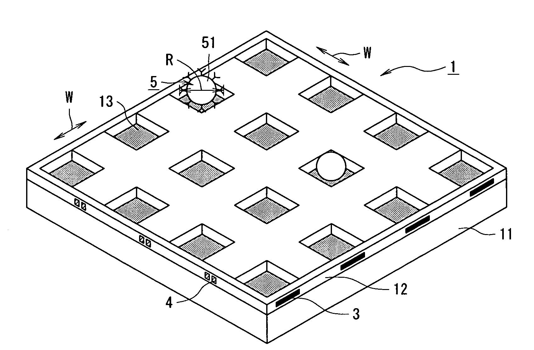
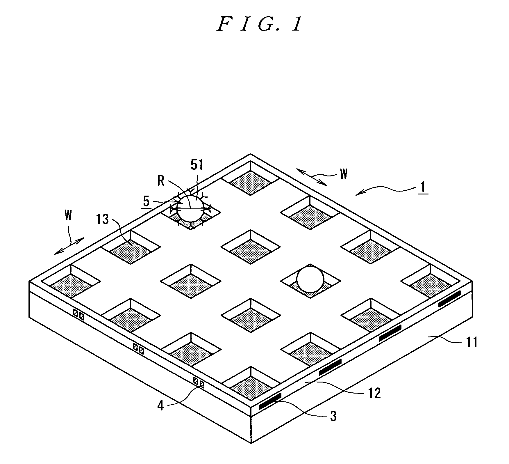
[0083]FIG. 1 is a schematic diagram showing a part of a sensor chip comprising the biosensor of the present invention. The composition of a sensor chip 1 includes semiconductor Hall devices as detector elements and a signal processing circuit of the semiconductor Hall devices. The sensor chip 1 is produced as described hereunder.

[0084]The sensor chip 1 is formed on a silicon substrate 11 by well-known CMOS (complementary metal oxide semiconductor) processes. Semiconductor Hall devices are formed at the bottom of recesses 13 in the surface of the sensor chip 1. Input and output of each of the semiconductor Hall devices is conducted through a gate electrode 30 and a metal wire 4.

[0085]After forming semiconductor Hall devices and a signal processing circuit on the silicon substrate 11 by CMOS processes, molecular receptors such as antigens, antibodies, DNA molecules or RNA molecules are immobilized on the surface of the sensor chip 1 treated by a silane coupling agent or the like.

[0086...

embodiment 2

[0130]Next, the circuit operation of the entire biosensor according to the second embodiment of the present invention will be described using the flowchart shown in FIG. 8. The configuration of the entire biosensor is the same as that shown in FIG. 6. However, the amplification circuit 81 in FIG. 6 further comprises a detector circuit for extracting only a frequency component from the output signals of the semiconductor Hall devices.

[0131]In a step S201, in a state where objects to be measured and magnetic molecules that include magnetic particles have been introduced onto a sensor chip, a magnetic field is generated by passing a direct current through a lower coil, whereby the magnetic molecules are attracted to the sensor chip surface.

[0132]In a step S202, the magnetic field originating from the lower coil is turned OFF.

[0133]In a step S203, a magnetic field is generated by passing a direct current through an upper coil, whereby magnetic molecules are attracted away from the senso...

embodiment 3

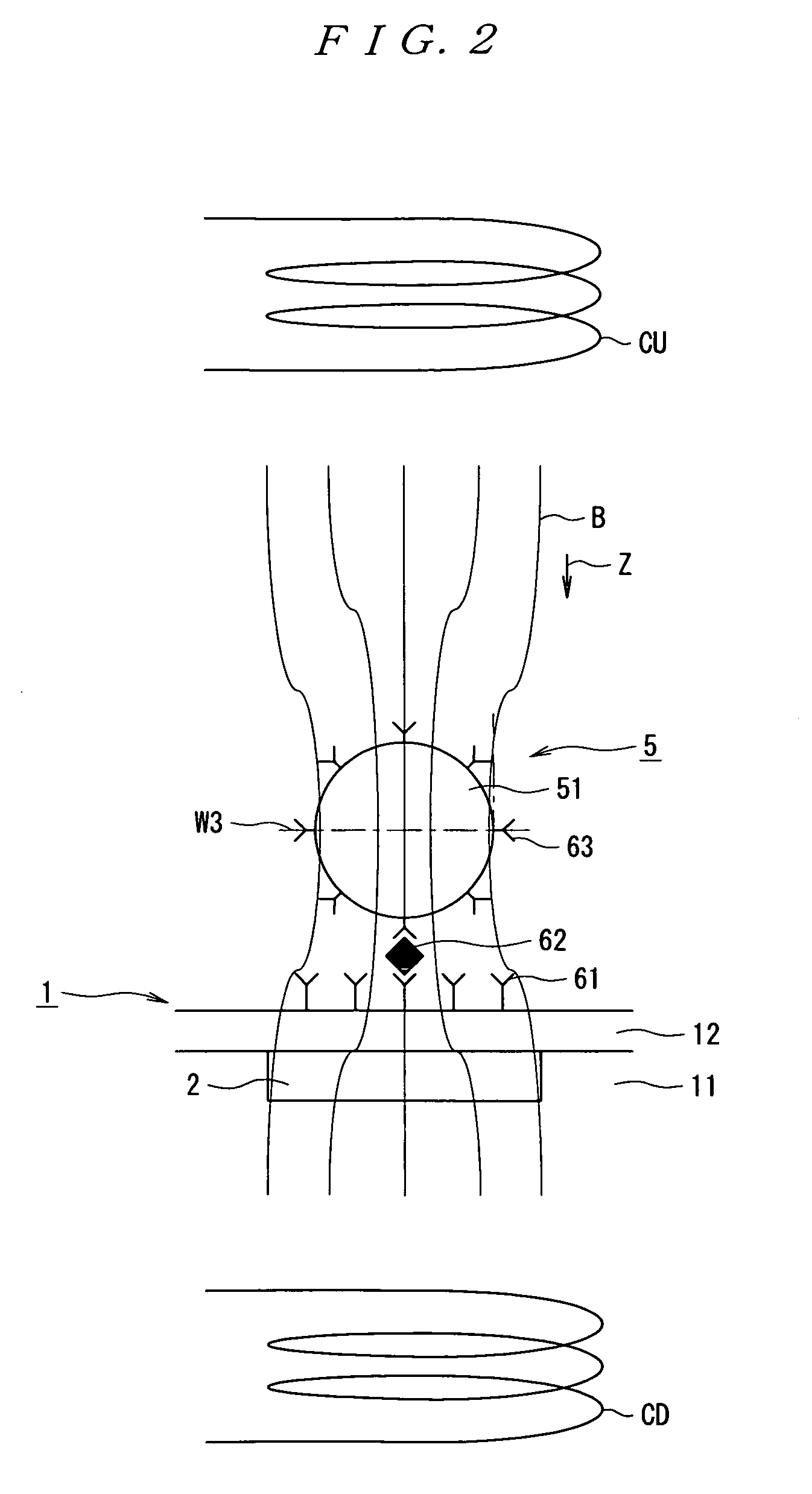
[0150]Next, the detection principles of a biosensor according to the third embodiment of the present invention will be described using FIG. 9. FIG. 9 is a view schematically showing a cross section of the vicinity of the semiconductor Hall device 2 of the sensor chip 1. The molecular receptors 61 composed of antibodies are immobilized on the surface of the semiconductor Hall device 2. The object to be measured 62 is bound specifically to one of the molecular receptors 61. Further, the magnetic particle 51 is bound to the object to be measured 62 through specific binding between the object to be measured 62 and one of the molecular receptors 63 that are composed of antibodies. The magnetic particle 51 and the molecular receptors 63 bind to each other to form the magnetic molecule 5.

[0151]The sensor chip 1 is arranged with its surface facing downward, and a rear coil CR (second magnetic field generation means) is provided. The intensity of a magnetic field generated by the rear coil C...


PUM

PropertyMeasurementUnit
distanceaaaaaaaaaa
distanceaaaaaaaaaa
voltageaaaaaaaaaa

Abstract

A biosensor not requiring washing of an unbonded label molecular by analyzing an object to be measured such as an antigen, an antibody, a DNA, and an RNA through magnetic field sensing. The biosensor is small in size, low in price, and high in sensing accuracy. Semiconductor Hall devices are arrayed two-dimensionally on the bottoms of recesses in the surface of a sensor chip to which bonded is a magnetic molecule with which a magnetic particle is labeled so as to sense the magnetic field produced along the sensor surface of the sensor chip. The surface area of each semiconductor Hall device is less than the maximum cross section of the magnetic molecule, and the intervals of the arrayed semiconductor Hall devices are larger than the diameter of the magnetic Hall molecule. Thus, the analysis accuracy is enhanced. An interconnection is used commonly to the semiconductor Hall devices, thereby reducing the size of the sensor.

Description

CROSS-REFERENCE TO RELATED APPLICATIONS[0001]This application is a National Stage application under 35 U.S.C. §371 and claims benefit under 35 U.S.C. §119(a) of International Application No. PCT / JP03 / 00847 having an International Filing Date of Jan. 29, 2003, which claims benefit of JP 2002-20095 filed on Jan. 29, 2002 and JP 2002-271410 filed on Sep. 18, 2002.TECHNICAL FIELD[0002]The present invention relates to a biosensor, a method for measuring magnetic molecules and a method for measuring objects to be measured, and more particularly to a biosensor, a method for measuring magnetic molecules and a method for measuring objects to be measured that are used for analyzing objects to be measured by measuring the amount of magnetic molecules.BACKGROUND ART[0003]In recent years clinical diagnosis and detection as well as genetic analysis is being carried out by immunological techniques or hybridization in which specific binding between specific pairs of molecules, such as binding of an...

Claims


Application Information

Patent Timeline
Patent Type & Authority Patents(United States)
IPC IPC(8): G01N33/536C12Q1/68G01N27/72G01N27/82G01N33/543
CPCG01N27/745G01N33/54373G01N33/54326
Inventor FUKUMOTO, HIROFUMINOMURA, MASAYUKI
Owner ASAHI KASEI KK
Why Eureka
Try Eureka