Mitigation of propagation of thermal runaway in a multi-cell battery pack

a multi-cell battery pack and thermal runaway technology, which is applied in the direction of several simultaneous battery arrangement, safety/protection circuit, electric devices, etc., can solve the problems the durability and overall life of batteries or cells, and the inability to achieve the acceleration, handling, performance, etc., to achieve the effect of reducing the range of electrical vehicles, reducing the cost of battery or cell replacement, and reducing the cost of replacemen

Active Publication Date: 2008-10-07
TESLA INC
View PDF3 Cites 146 Cited by
  • Summary
  • Abstract
  • Description
  • Claims
  • Application Information

AI Technical Summary

Benefits of technology

[0015]One advantage of the present invention may be that it provides a novel and improved system for mitigation of a thermal runaway event in a multi-cell battery pack.
[0016]Still a further advantage of the present invention may be that it provides a system for mitigation of a thermal runaway event for use in an electric vehicle.
[0017]Yet another advantage of the present invention may be that it provides a system for mitigation of propagation of a thermal runaway event in a multi-cell battery pack that slows the temperature rise within the battery pack and hence increases the range and performance of the vehicle.
[0018]Still another advantage of the present invention may be that it provides a method of maximizing the longevity of the battery pack by thermally managing the cooling and heating of the battery pack.
[0019]Yet another advantage of the present invention may be that it provides a system for mitigating the propagation of a thermal runaway event that includes a plurality of sensors and passive and active cooling systems to ensure an overheating cell does not propagate to adjacent cells.
[0020]Yet another advantage of the present invention may be that it provides a system for mitigating propagation of a thermal runaway event by having the capability of detaching or isolating overheating cells that have over voltages, under voltages, over current or under current from the other cells of the battery pack.

Problems solved by technology

Furthermore, many of these prior art electric vehicles need to be physically large and heavy to accommodate all of these batteries, such that these vehicles are not capable of achieving necessary acceleration, handling, performance and the extended range needed for an electric vehicle to become a feasible option for public purchase and use.
Many prior art electric vehicles that were of normal size and not overly heavy, would have a very small range, thus reducing the feasibility for large mass selling of such vehicles to the consuming public.
Furthermore, many of these prior art electrical vehicles which use such batteries had problems with protecting the occupants in the vehicle from the high voltage components and high temperatures that emanated from such high voltage components and still provide a vehicle that moves at a acceptable speeds compared to that of a gasoline or diesel internal combustion engine equipped vehicle.
Some of these prior art electrical vehicles have had problems with their batteries overheating, thus reducing the range of the electrical vehicle and the durability and overall life of the batteries or cells that are part of the battery pack systems within the prior art electric vehicle.
Generally, batteries or cells are arranged within many prior art vehicles that operate with high power output which increases the temperature and hence may reduce longevity of the prior art batteries.
The use of the heavy and high voltage battery systems in prior art electrical vehicles requires a lot of maintenance to keep the batteries operating due to the high temperatures at which the battery pack systems tend to operate.
However, many of these prior art heat reduction systems for the batteries are not very efficient and do not provide an efficient system for balancing and removing heat or adding heat to the batteries.
Hence, many prior art systems may suffer from overheating or overcooling, thus reducing the durability and longevity of the batteries and hence the range of the electric vehicle.
Furthermore, in some of these prior art vehicles if one battery cell got too hot it would propagate and lead to a thermal runaway of the entire battery pack and all of the batteries therein, thus greatly reducing the longevity and the ability of the cells to hold a charge or completely destroying the battery pack.

Method used


Image

  • Mitigation of propagation of thermal runaway in a multi-cell battery pack
  • Mitigation of propagation of thermal runaway in a multi-cell battery pack
  • Mitigation of propagation of thermal runaway in a multi-cell battery pack

Examples


Embodiment Construction

)

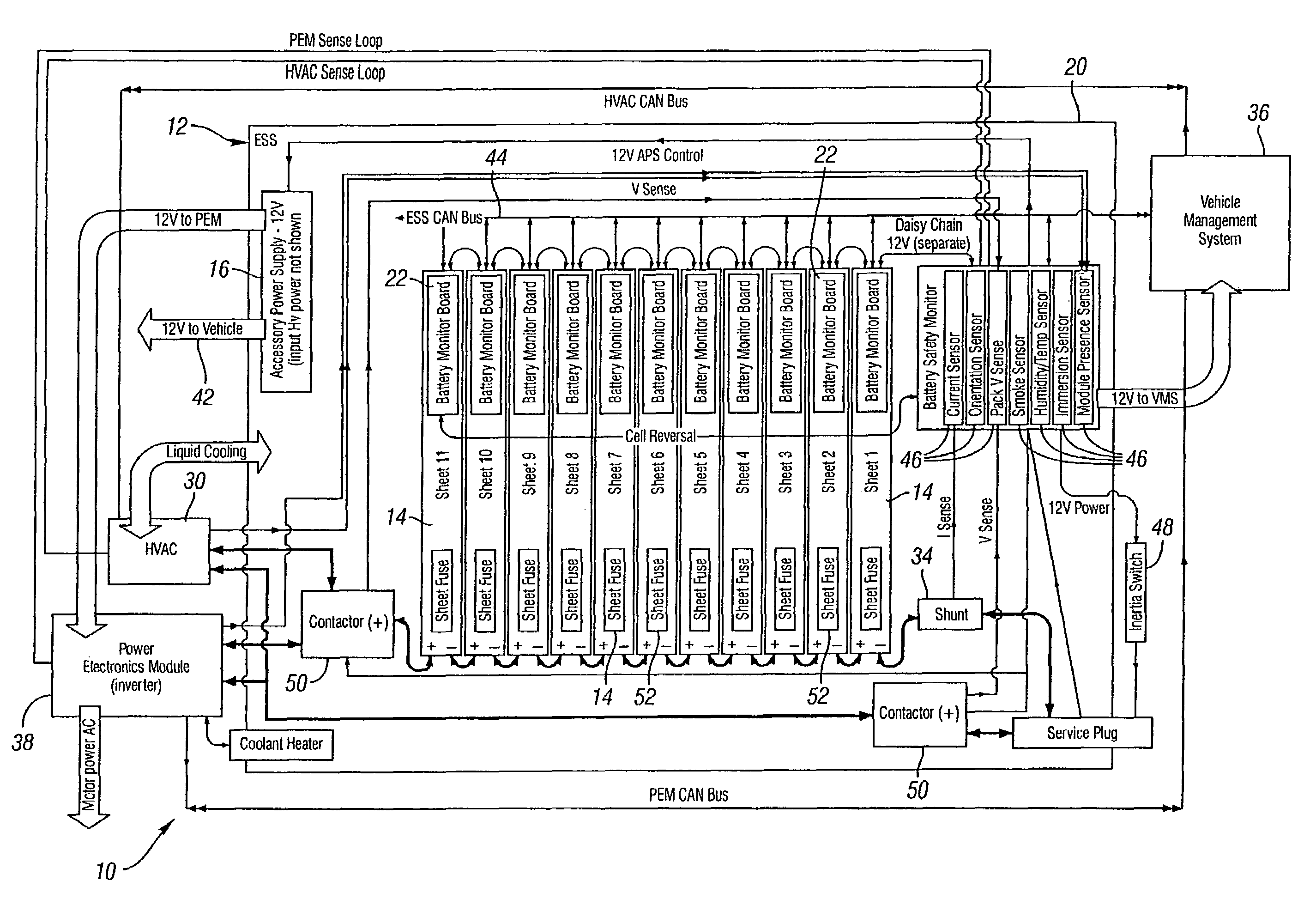
[0031]Referring to the drawings, a system 10 for mitigation of propagation of a thermal runaway event in a multi-cell battery pack for use in an energy storage system (ESS) 12 is shown. The energy storage system or battery pack 12 is generally comprised of a predetermined number of battery modules or sheets 14, a main control and logic PSB and a twelve volt power supply 16. In one contemplated embodiment the energy storage system 12 will have eleven battery modules or sheets 14 which are capable of producing approximately 375 volts DC. This nominal voltage will operate an electric vehicle that may be capable of traveling many miles without recharging and is capable of delivering enough power and acceleration for everyday driving use. In one contemplated embodiment the ESS 12 may be capable of storing enough energy that the electric vehicle may travel approximately 200 miles or more without recharging. However, it should be noted that it is also contemplated that the electric vehicl...


PUM


Abstract

A method of mitigating propagation of a thermal event in an energy storage system having a plurality of cells is disclosed. The method includes the steps of identifying the heat sources within the energy storage system and plurality of cells. The method then controls a temperature of the energy storage system and plurality of cells and also detects predetermined conditions within the energy storage system. The method then performs a predetermined action based on when one of the predetermined conditions is detected. A plurality of sensors and switches along with associated hardware or software will be used to control the temperature of the energy storage system upon detection of predetermined conditions involving overheating, over current, over voltage of the like.

Description

BACKGROUND OF THE INVENTION[0001]1. Field of the Invention[0002]The subject invention generally relates to mitigation of a thermal runaway event and more particularly relates to the mitigation of propagation of a thermal runaway event in a multi-cell battery pack for use in an electric vehicle.[0003]2. Description of Related Art[0004]It is well known in the prior art to use all electric vehicles to provide transportation for occupants. Many of these prior art electric vehicles carry several thousand pounds of nickel metal hydride batteries to achieve a long range electric vehicle for everyday use by consumers. Furthermore, many of these prior art electric vehicles need to be physically large and heavy to accommodate all of these batteries, such that these vehicles are not capable of achieving necessary acceleration, handling, performance and the extended range needed for an electric vehicle to become a feasible option for public purchase and use. Many prior art electric vehicles tha...

Claims


Application Information

Patent Timeline
Patent Type & Authority Patents(United States)
IPC IPC(8): G06F19/00H02J7/00
CPCB60L3/0046B60L11/1879H01M10/486H01M10/5004H01M10/5016H01M10/503H01M10/5057H01M10/5067H01M10/5095H02J7/0026B60L11/1866Y02T10/7061B60L2240/545B60L2240/547B60L2240/549H02J2007/0037H02J2007/004Y02T10/7005Y02T10/7055H01M10/625H01M10/663H01M10/6563H01M10/6556H01M10/643H01M10/613B60L58/22B60L50/64H02J7/00306H02J7/00302B60L58/26H02J7/00308H02J7/00309H02J7/0013Y02T10/70Y02E60/10
Inventor BERDICHEVSKY, EUGENE MICHAELCOLE, PHILIP DAVIDHEBERT, ARTHUR JOSEPHHERMANN, WESTON ARTHURKELTY, KURT RUSSELLKOHN, SCOTT IRALYONS, DAVID FREDERICKSTRAUBEL, JEFFREY BRIANMENDEZ, NOEL JASON
Owner TESLA INC
Why Eureka
Try Eureka